Tidal/water current electrical generating system

a technology of electrical generating system and tide water, which is applied in the direction of electric generator control, machines/engines, mechanical equipment, etc., can solve the problems of structural failure, impracticality, and structural problems of propellers, and achieve the effect of reducing the strain on flexible electrical cables

Inactive Publication Date: 2009-06-11
SEAR WALTER EDMOND
View PDF28 Cites 22 Cited by
  • Summary
  • Abstract
  • Description
  • Claims
  • Application Information

AI Technical Summary

Benefits of technology

[0015]The present invention is designed to overcome these difficulties by providing apparatus and systems to provide an economic, safe and efficient system for the generation of electrical power. Because of the design of the impeller, significantly less diameter is needed in comparison to a propeller of equal torque. The draft will be far less, allowing the device to be used in much shallower water.
[0017]The impeller is designed as a conical device with a semi-hemispherical front hub at its center. Radiating backward from this hub, axial to the flow of water, almost parallel vanes increase in their angle to the flow of water as the diameter of the cone increases, terminating in an almost 90 degree angle to the flow as they approach the base of the cone. The thickness of the vane walls increases as the area pressure increases, for structural reasons. The depth of the vanes from tip to base is also increased to provide a greater and greater surface area to the flow of the water. A center shaft is affixed to the impeller with suitable bearings and seals to sustain the impeller's rotation.
[0023]Because of the two magnets involved, one in the stator and one in the rotor, greater magnetic flux is generated and hence, greater electrical output is obtained. These magnetic units, both in the stator and the rotor, can be compounded up to the limits of the physical space. By placing the rotor magnets axially, two ranks of stator magnets can face the north and south poles of the rotor to produce sine waves 180 degrees out of phase, or by placing the stator magnets one segment apart from the first rank of stators, a doubling of the voltage output can be produced, in phase. This, together with the decrease or elimination of the hysteresis losses, will produce a more efficient alternator / generator.
[0028]Axially, along the entire length of this waterproof container, heat conducting fins are attached. These fins serve two purposes; first to keep the entire device pointed into the flow of water, and, secondly, to dissipate the heat generated in the alternator / generating housing. This heat is generated by the I square R losses, eddy currents and hysterises losses and friction. The fins will serve the same purpose as elephant ears—to provide more area for heat dissipation into the surrounding water.
[0033]The generating device is equipped with a swivel bearing which allows the generating device with the impeller assembly attached, to rotate through approximately 210 degrees on this mount. Stops are provided to prevent the device from rotating a full 360 degrees, thus reducing the strain on the flexible electrical cable to the shore. This is also to accommodate the changing of the tides. By allowing the device, due to the fins on the generator housing, to always point into the flow of the water, some additional electrical energy can be generated even during a change of tides. It also provides additional protection against any radical changes in the water flow by adjusting to these changes.

Problems solved by technology

These have been proven to be impractical because of high maintenance due to the hostile environment of salt water of even fresh water, environmental problems and general price to output inefficiencies.
The use of propellers rather than impellers has created structural problems with the propellers, which are subject to structural failure due to the mechanical stress and the flotsam and jetsam which is floating in the water.
They also might create environmental problems because of the potential damage to fish and other aquatic life.
Propellers require a large draft and might also present a hazard to navigation as well as to people who may be swimming in the water.
This generally leads to a less efficient design.
The alternator / generator, which is the most expensive part of the system, must have a drive shaft extending from the propeller into the generating device, which is subject to leakage around the seals, resulting in damage to the generating device.
The subsequent ridged mounting of the entire device to its mooring makes it less efficient as far as accommodating variations in the flow of water and it makes the entire mechanism more subject to damage from debris in the water, including large fish.

Method used


Image

  • Tidal/water current electrical generating system
  • Tidal/water current electrical generating system
  • Tidal/water current electrical generating system

Examples


Embodiment Construction

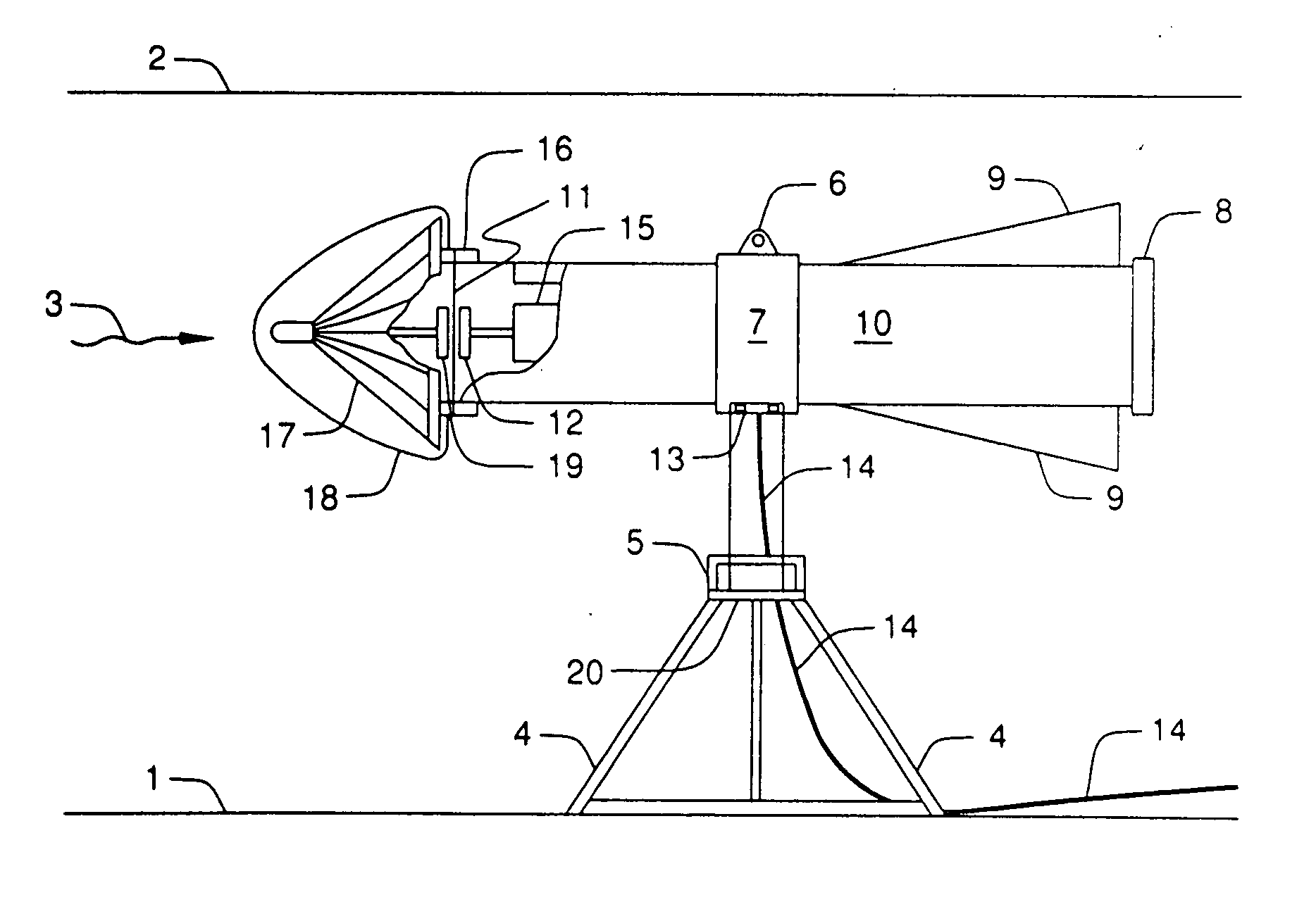
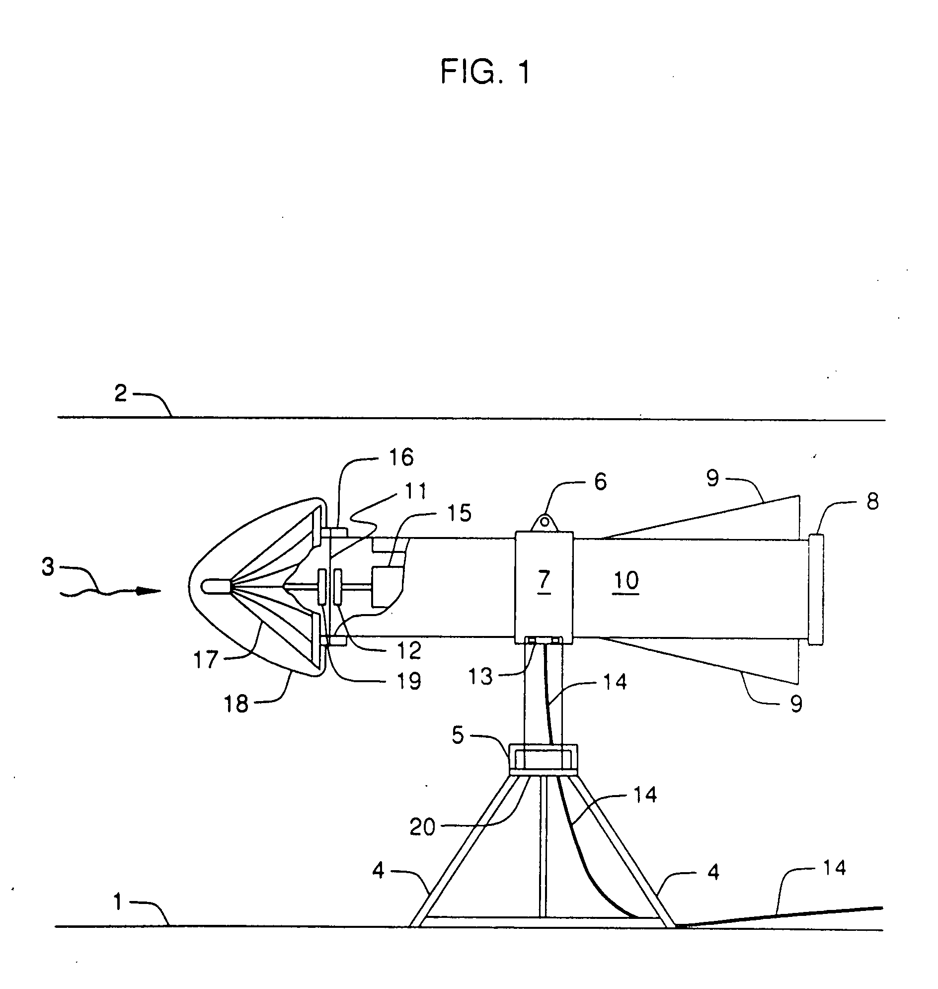
[0034]FIG. 1 is an overall description of the invention. #1 in the drawing represents the river bed upon which the invention is placed. #2 depicts the surface of the body of water, below which the device is placed. #3 depicts the direction of flow of the body of water. #4 depicts the mechanical mounting of the device, which can be a pylon or a pile driven into the bed of the body of water. #5 is a thrust or other suitable bearing which allows the upper structure of the alternator / generator with the attached impeller assembly to rotate freely. This is restricted by stops to limit the amount of rotation, thereby reducing the strain on the flexible power cable leading to shore.

[0035]#6 is a launching ring to facilitate the lowering and raising of the device into and out of the water. #7 is a mounting saddle which mechanically attaches the base pedestal to the generating pod. #8 is the end cap to the waterproof housing of the generating device to allow access for maintenance when the in...


PUM


Abstract

An integral system to utilize the flow of water, fresh or ocean, to generate electric power from river flow or tidal currents, consisting of three parts, an especially designed impeller to convert the water flow into rotary mechanical motion, a totally encapsulated alternator / generator, and a pedestal upon which the entire device is mounted which is set into the sea bed or river bed and which is fitted with a swivel bearing which allows a limited rotation of the alternator / impeller assembly, and with fins to keep the impeller pointed into the existing current and which also serve as heatsinks for the alternator / generator.

Description

BACKGROUND OF THE INVENTION[0001]References cited:U.S. Patent Documents[0002]7,199,484 B2Apr. 3, 2007Brashears7,116,005 B2Oct. 3, 2006Corcoran, III4,026,587May 31, 1977Hultman et al.5,043,592Aug. 27, 1991Hochstrasser5,499,013Mar. 12, 1996Konotchick5,936,321Aug. 10, 1999Kameoka et al.5,929,611Jul. 27, 1999Scott et al.US 2005 / 0285407 A1Dec. 29, 2005Davis et al.[0003]Heretofore, there have been a variety of proposals involving the use of river flow or tidal flow of natural waterways to provide the power source to be converted into rotary energy to operate an electrical generating device. These have been proven to be impractical because of high maintenance due to the hostile environment of salt water of even fresh water, environmental problems and general price to output inefficiencies. The use of propellers rather than impellers has created structural problems with the propellers, which are subject to structural failure due to the mechanical stress and the flotsam and jetsam which is f...

Claims


Application Information

Patent Timeline
Patent Type & Authority Applications(United States)
IPC IPC(8): F03B13/10
CPCF03B13/10F03B13/264Y02E10/28F05B2240/97F03B17/061Y02E10/30Y02E10/20
Inventor SEAR, WALTER EDMOND
Owner SEAR WALTER EDMOND
Why Eureka
Try Eureka