

Belt member, transfer unit incorporating same, image forming apparatus incorporating same, and method of evaluating same
- Summary
- Abstract
- Description
- Claims
- Application Information
AI Technical Summary
Benefits of technology
Problems solved by technology
Method used
Image

Examples
first exemplary embodiment
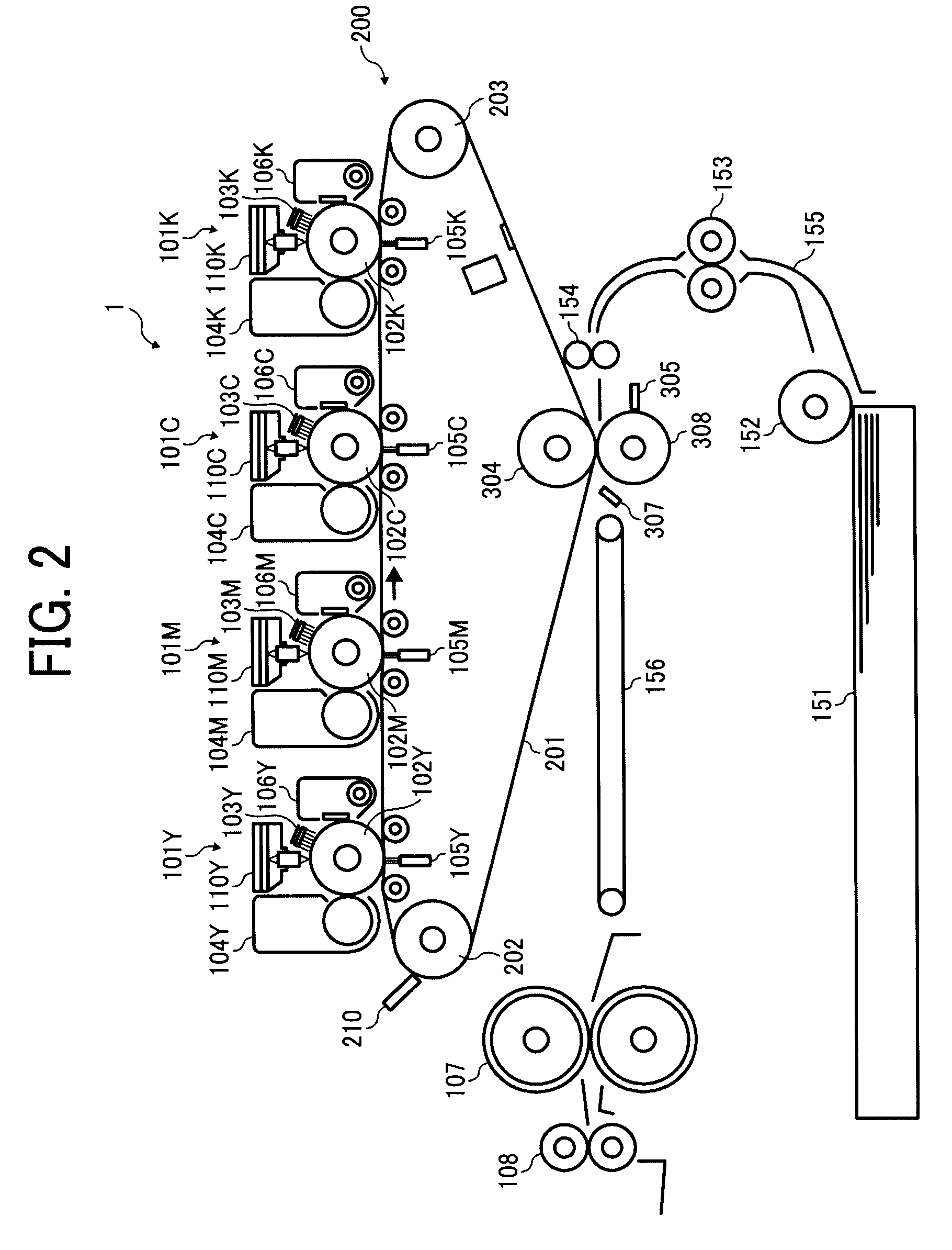
[0058]FIG. 2 is a drawing of a schematic configuration of an image forming apparatus 1 according to a first exemplary embodiment of the present invention.
[0059]The image forming apparatus 1 of FIG. 2 corresponds to a printer, copier, facsimile machine, etc. and employs a tandem type indirect transfer system. In other words, the image forming apparatus 1 includes multiple image forming units 100Y, 101M, 101C, and 101K that are disposed along an intermediate transfer belt 201 that serves as an intermediate transfer member. The image forming apparatus 1 includes a transfer unit 200 at a center part thereof. The transfer unit 200 includes the intermediate transfer belt 201 in a form of an endless belt member. The intermediate transfer belt 201 is wound around multiple supporting rollers, which are a first supporting roller 202, a second supporting roller 203, and a third supporting roller 304. The intermediate transfer belt 201 is rotationally conveyable in a clockwise direction in FIG....
example 1
[0127]In Example 1, an intermediate transfer belt 201 having a single layer structure was used to examine attenuation of potential of the intermediate transfer belt 201. The single layer of a polyimide resin having a thickness of 80 μm was formed by adjusting a conductive additive amount of carbon black by using the centrifugal molding method and changing the resistance of the intermediate transfer belt 201.
[0128]FIG. 6 is a graph showing potential attenuation of the intermediate transfer belts 201 having different resistivities. The volume resistivity was measured with a resistance measuring instrument, HIRESTA-UP (manufactured by Mitsubishi Chemical Corporation). The measurement condition are as follows.
[0129][Volume Resistivity Measurement Method / Condition]
[0130]Resistance measuring instrument: HIRESTA-UP (manufactured by Mitsubishi Chemical Corp.);
[0131]Probe: URS probe;
[0132]Object Supporting Member: REGI TABLE, with conductive rubber having a thickness of 1 mm;
[0133]Measuremen...
example 2
[0160]The differences between amounts of resistivity changes of the outer and inner surfaces of the intermediate transfer belt 201 and evaluation results of images are shown in Table 2 and a graph in FIG. 14. Reference images for evaluation of white spots and horizontal white banding were specified in advance, and the evaluation was conducted to rank the results based on the reference images. Rank 5 represents a highest rank indicating good image performance, and as the level of the rank descends, the image quality degrades. Rank 4 is set to be a threshold or border of acceptance.
TABLE 2Thick-Δ (OuternessandResistivityofInnerof SurfaceSurfaceVolumeSurfaceLateralLayerLayerResistivityResistivityWhiteWhiteMaterial(μm)(ρv)(ρs)SpotsBandingEx. 2Nil (Single09.501.55Layer)11.91.89.50.032511.92.29.50.064511.94.69.60.174.5511.96.29.60.184.5512.81.89.70.314.75512.84.59.80.9654.512.86.310.31.25314 or above2.410.61.452
[0161]Further, the image evaluation was conducted with the image forming appar...
PUM
 Abstract
Description
Claims
Application Information