Method of progressively prototyping and validating a customer's electronic system design

a technology of electronic system design and prototyping, applied in the direction of cad circuit design, program control, instruments, etc., can solve the problems of difficult design, debugging, verification and validation of a system that includes a user design integrated with one or more third party ips, logic gates and embedded software are extremely difficult to create, and user designs specified by behavior simulation models are generally difficult to design, debugging, and verifying and validating systems. achieve the effect of cost-saving in the test pattern

Inactive Publication Date: 2009-06-11
INPA SYST
View PDF8 Cites 4 Cited by
  • Summary
  • Abstract
  • Description
  • Claims
  • Application Information

AI Technical Summary

Benefits of technology

[0028]For those customers already in possession of a test pattern generator and a customer simulation software tool capable of simulating and verifying the hierarchical design elements, the method simply provides a vector generation too

Problems solved by technology

In the prior art, designing, debugging, verifying and validating a system that includes a user design integrated with one or more third party IPs is generally difficult, as the user often starts with designing a behavior description or a simulation model of the IP with incomplete control over the IPs logical behavior at the interfaces between the user design and the IPs.
In addition, user designs that are specified by behavior simulation models, logic gates and embedded software are extremely difficult to create.
In such a system, it is also difficult to isolate system faults.
For example, it is difficult to discover errors within an audio

Method used


Image

  • Method of progressively prototyping and validating a customer's electronic system design
  • Method of progressively prototyping and validating a customer's electronic system design
  • Method of progressively prototyping and validating a customer's electronic system design

Examples


Embodiment Construction

[0044]The description herein, in conjunction with the drawings, merely focus on one or more currently preferred embodiments of the present invention and also describe some exemplary optional features and alternative embodiments. The description and drawings are presented to illustrate and, as such, are not limitations of the present invention. Thus, upon consideration of this disclosure, those of ordinary skill in the art would readily recognize variations, modifications, and alternatives. Such variations, modifications and alternatives should be understood to be also within the scope of the present invention.

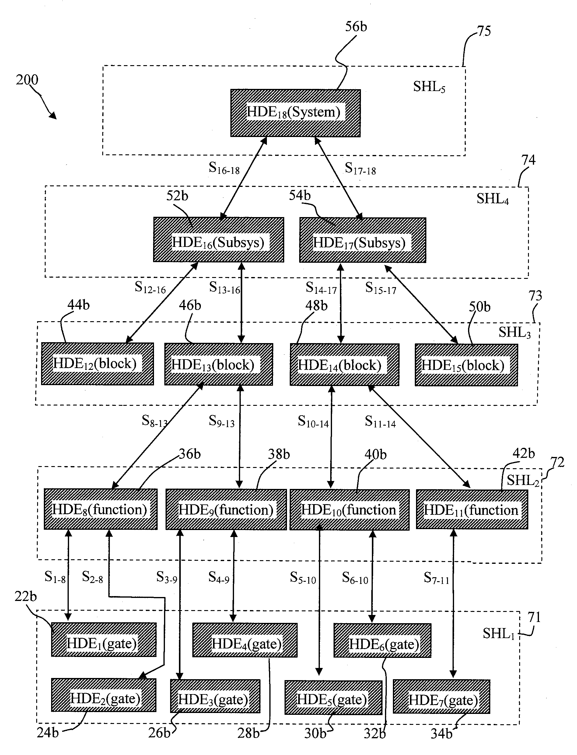
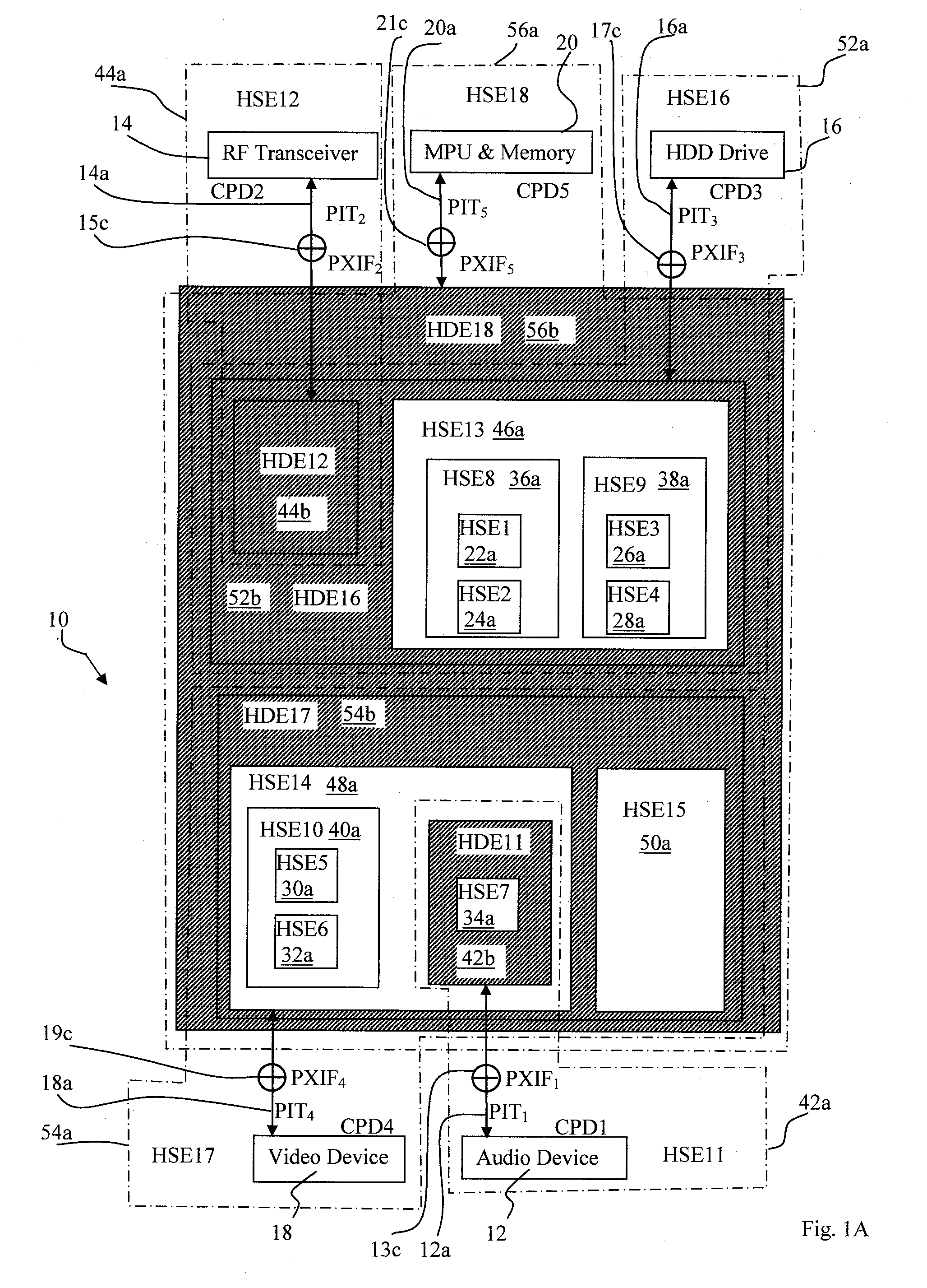
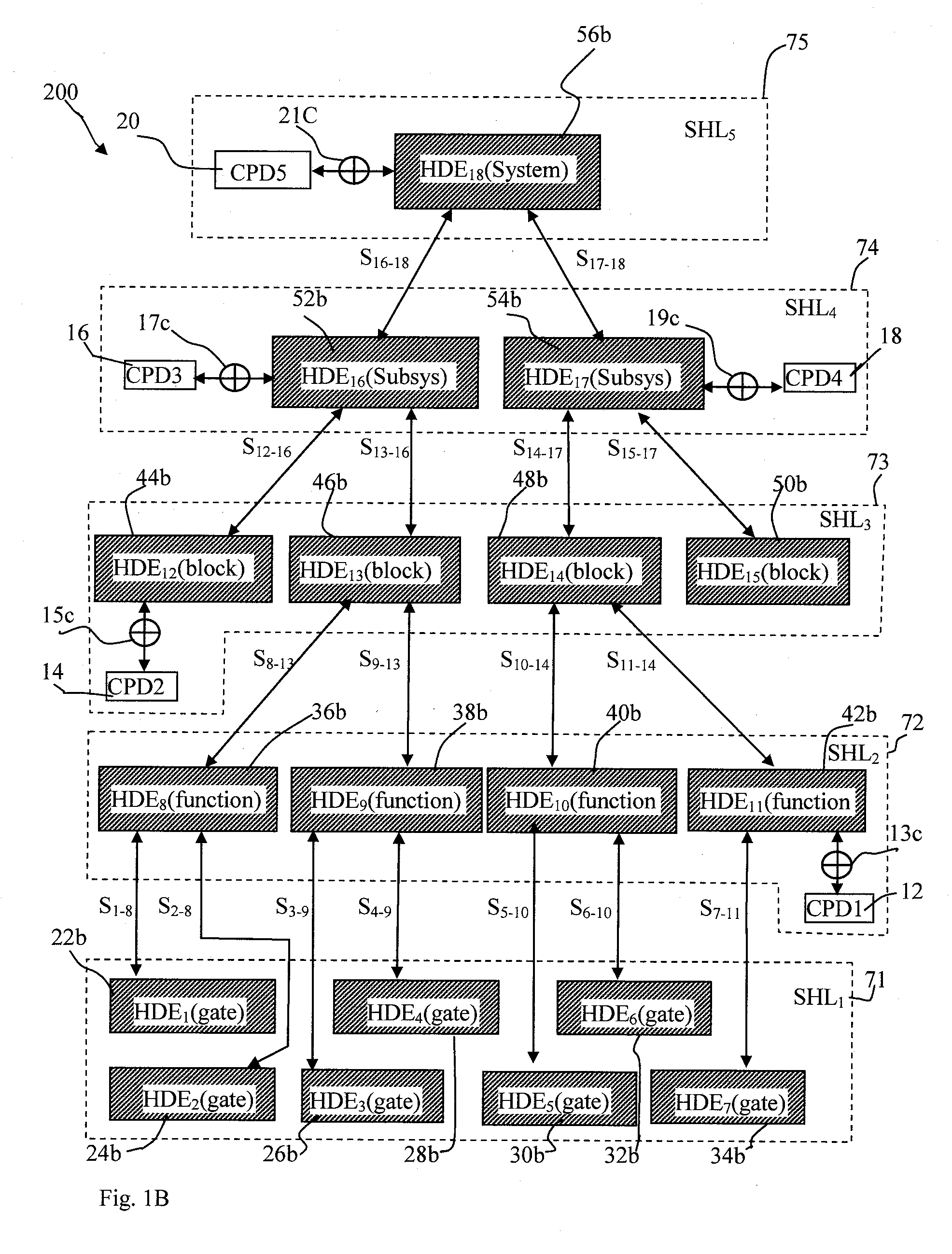
[0045]FIG. 1A illustrates the end goal of the present invention that is a customer's verified and validated electronic system prototype 10 including a number of coupled customer's existing peripheral devices (CPD) CPD112, CPD214, CPD316, CPD418 and CPD520 all in a hardware environment. FIG. 1B illustrates, as a side-product of the end goal of the present invention, the customer...


PUM


Abstract

A method for prototyping and validating a customer's electronic system design (ESD) with design data is proposed. The design data is partitioned into hierarchical design elements (HDEs) plus their respective test benches. The ESD couples with customer's customer peripheral devices CPDs via their peripheral interface terminals PITs thus forming interconnected hierarchical system elements (HSEs) interacting with one another according to a functional validation specification. The HSEs form numerous system hierarchy levels (SHLs). The method includes:
    • a) Providing a reprogrammable logic device (RPLD) with an RPLD-interface and programmable external interfaces PXIFs respectively connected to the PITs.
    • b) Providing a simulation software tool.
    • c) Disabling all PXIFs via RPLD-interface. (For each disabled PXIF, identifying HDEs connected to the PXIF and appending their test benches with stimuli and responses to form appended test benches.
    • d) Progressively verifying and validating all HSEs against the functional validation specification following an upward movement along the SHLs.

Description

FIELD OF INVENTION[0001]The present invention relates generally to design and validation methods and techniques applicable to designing complex electronic circuits. In particular, the present invention relates to a methodology for verifying and validating electronic circuit designs that are particularly applicable to system-on-a-chip and ultra large scale integrated circuit type electronic circuits.BACKGROUND OF THE INVENTION[0002]As the level of integration continues to advance, many complex electronic logic systems can now be implemented on a single integrated circuit (IC). Such an IC, often known as “system on a chip (SoC)” or “ultra large scale integrated circuit (ULSI)” in the art, includes multiple complex components (e.g., micro-processor, digital signal processor, peripheral and memory controllers), many of which may be individually obtained as “off-the-shelf” electronic circuit designs from a numerous vendors in the market. These electronic circuit designs are known as “IPs...

Claims


Application Information

Patent Timeline
IPC IPC(8): G06F17/50
CPCG06F2217/86G06F17/5027G06F30/331G06F2117/08
Inventor HUANG, THOMAS B.CHANG, CHIOUMIN M.
Owner INPA SYST
Why Eureka
Try Eureka