
Control method for temporarily increasing the exhaust gas temperature

Inactive Publication Date: 2009-06-18
FORD GLOBAL TECH LLC
View PDF18 Cites 13 Cited by
  • Summary
  • Abstract
  • Description
  • Claims
  • Application Information

AI Technical Summary

Benefits of technology

[0006]This invention is directed to providing a control method for increasing the exhaust gas temperature, in which dilution of the engine oil can be largely avoided.

Problems solved by technology

One problem of post-injection is that a proportion of the additional fuel injected is not burned, but is precipitated on the inside walls of the cylinder and can get into the engine oil.
The disadvantage of an unwanted dilution of the engine oil with fuel thereby has to be accepted in order to obtain the advantage of an increase in the exhaust gas temperature.
A major problem, especially in the case of diesel engines, is the extremely difficult coupling between the exhaust gas recirculation control and the separate boost pressure control.
This means that it is currently not possible to regulate one of the two parameters without upsetting or having a detrimental effect on the adjustment of the other parameter.
This requires separate control elements for each of them, which have to be adjusted separately and which are extremely cost-intensive.

Method used


Image

  • Control method for temporarily increasing the exhaust gas temperature
  • Control method for temporarily increasing the exhaust gas temperature
  • Control method for temporarily increasing the exhaust gas temperature

Examples


Embodiment Construction

[0014]In the respective drawings, the same parts are always provided with the same reference numerals, for which reason these parts are generally described only once.

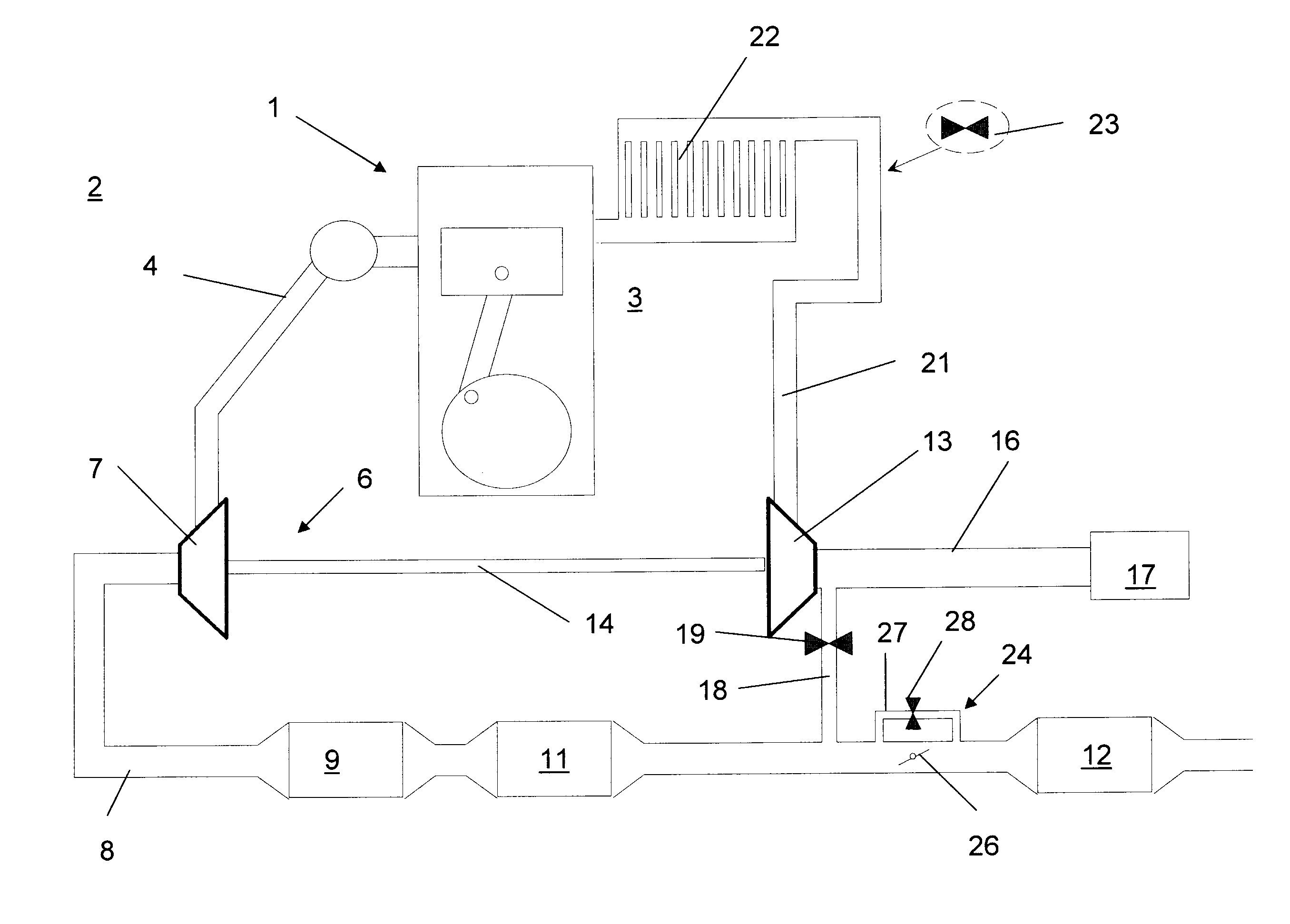
[0015]FIG. 1 shows a turbocharged internal combustion engine 1 having an exhaust side 2 and an intake side 3. The internal combustion engine 1 may be embodied as a single or a multi-cylinder engine, it being naturally also possible to configure the internal combustion engine as a V-engine or in some other form. The exemplary embodiment shown relates to a diesel engine, but is not intended to be limited to diesel engines.

[0016]The increase in the exhaust gas temperature in this exemplary internal combustion engine is achieved by a control method, which is described further below.

[0017]An exhaust pipe 4, which delivers the exhaust gases produced in the internal combustion engine 1 to a turbocharger 6 or to its turbine side 7, is assigned to the exhaust side 2, the exhaust gases flowing through the turbine side 7. From the...


PUM


Abstract

The invention relates to a control method for increasing the exhaust gas temperature of an internal combustion engine, which has at least one exhaust gas aftertreatment device in its exhaust tract, and which has an exhaust gas recirculation system, to which a regulating system is assigned. In order to increase the temperature of the exhaust gas and avoid engine oil dilution due to retarded post-injections, the regulating system increases the exhaust gas back-pressure while maintaining an exhaust gas recirculation rate, and increases a fuel injection quantity into the combustion chamber during the main injection.

Description

BACKGROUND AND SUMMARY OF THE INVENTION[0001]The invention relates to a control method for increasing the exhaust gas temperature of an internal combustion engine, which has at least one exhaust gas aftertreatment device in its exhaust tract, and which has an exhaust gas recirculation system, to which a regulating system is assigned.[0002]EP 0 521 411 A1 discloses an exhaust gas pipe of an internal combustion engine, having at least one catalytic converter arranged in the exhaust pipe, and an adjustable throttle element arranged in said pipe. The throttle element is arranged with a fixed upstream end adjacent to a side wall of the exhaust pipe. A moveable downstream end is arranged so as to form a gap between it and an opposing side wall when the internal combustion engine is cold.[0003]U.S. Pat. No. 7,131,271 B2 is concerned with a method for controlling a low-pressure exhaust gas recirculation of an internal combustion engine. The exhaust gas recirculation system has a throttle va...

Claims


Application Information

Patent Timeline
IPC IPC(8): F01N3/00
CPCF02D41/0065F02D41/024F02D41/40F02M25/0718F02D2250/11Y02T10/44Y02T10/26Y02T10/47F02D41/0255F02M25/0754F02M26/15F02M26/47Y02T10/12Y02T10/40
Inventor VIGILD, CHRISTIAN WINGEKUENSTLER, JOHANNESROETTGER, DANIELKARVOUNIS, EVANGELOS
Owner FORD GLOBAL TECH LLC
Learn More