
Chip For Cell Electrophysiological Sensor, Cell Electrophysiological Sensor Using The Same, and Manufacturing Method of Chip for Cell Electrophysiological Sensor

a cell electrophysiological sensor and cell electrophysiological technology, applied in the field of cell electrophysiological sensor chip manufacturing method, can solve the problems of low rate of sample cell b>10/b> sucked accurately, poor flow of electrolyte solution flowing in and out of through-hole, etc., to achieve enhanced reduced resistance loss of fluid, and enhanced effect of sample cell trapping ra

Inactive Publication Date: 2009-06-18
PANASONIC CORP
View PDF9 Cites 10 Cited by
  • Summary
  • Abstract
  • Description
  • Claims
  • Application Information

AI Technical Summary

Benefits of technology

[0010]The invention is intended to encourage the flow of electrolyte solution flowing in and out of the through-hole, and to enhance the trapping rate of sample cells.
[0012]As a result, the electrolyte solution flows easily in and out of the through-hole, and the trapping rate of sample cells can be enhanced.
[0013]Specifically, the opening of the through-hole is formed in a curved surface smoothly linking with the substrate surface, and changes of sectional area of passage from the electrode jar to the inside of the through-hole are moderate, and the resistance loss of fluid is decreased. Hence, the electrolyte solution is allowed to flow easily in and out of the through-hole, and the sample cell is trapped accurately, and the trapping rate is enhanced.

Problems solved by technology

However, in the conventional cell electrophysiological sensor 1, the flow of electrolyte solution 9 flowing in and out of the through-hole 5 is poor, and the rate of trapping the sample cell 10 is low.
As a result, the sample cell 10 cannot be sucked accurately, and the trapping rate declines.

Method used


Image

  • Chip For Cell Electrophysiological Sensor, Cell Electrophysiological Sensor Using The Same, and Manufacturing Method of Chip for Cell Electrophysiological Sensor
  • Chip For Cell Electrophysiological Sensor, Cell Electrophysiological Sensor Using The Same, and Manufacturing Method of Chip for Cell Electrophysiological Sensor
  • Chip For Cell Electrophysiological Sensor, Cell Electrophysiological Sensor Using The Same, and Manufacturing Method of Chip for Cell Electrophysiological Sensor

Examples


embodiment 1

Preferred Embodiment 1

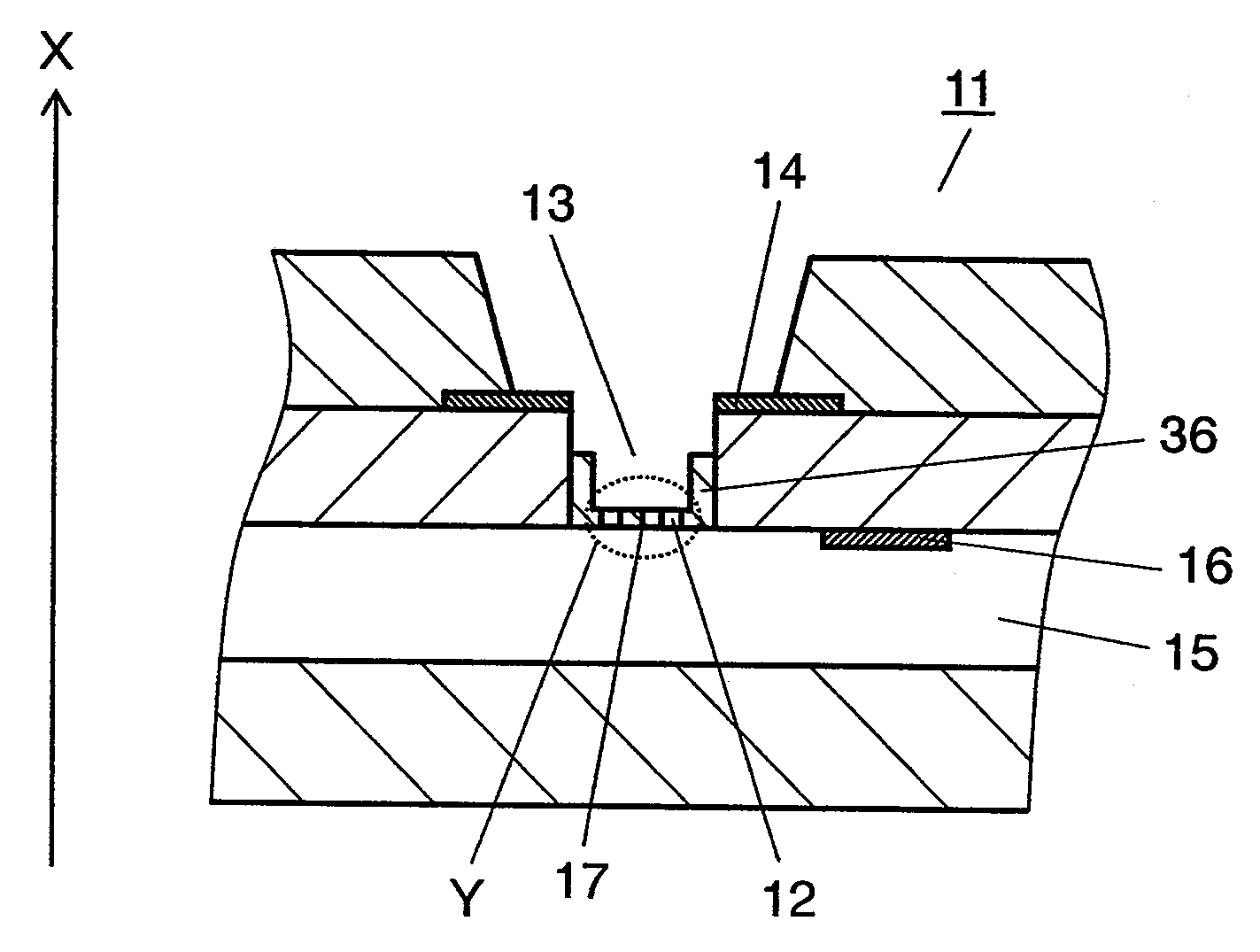
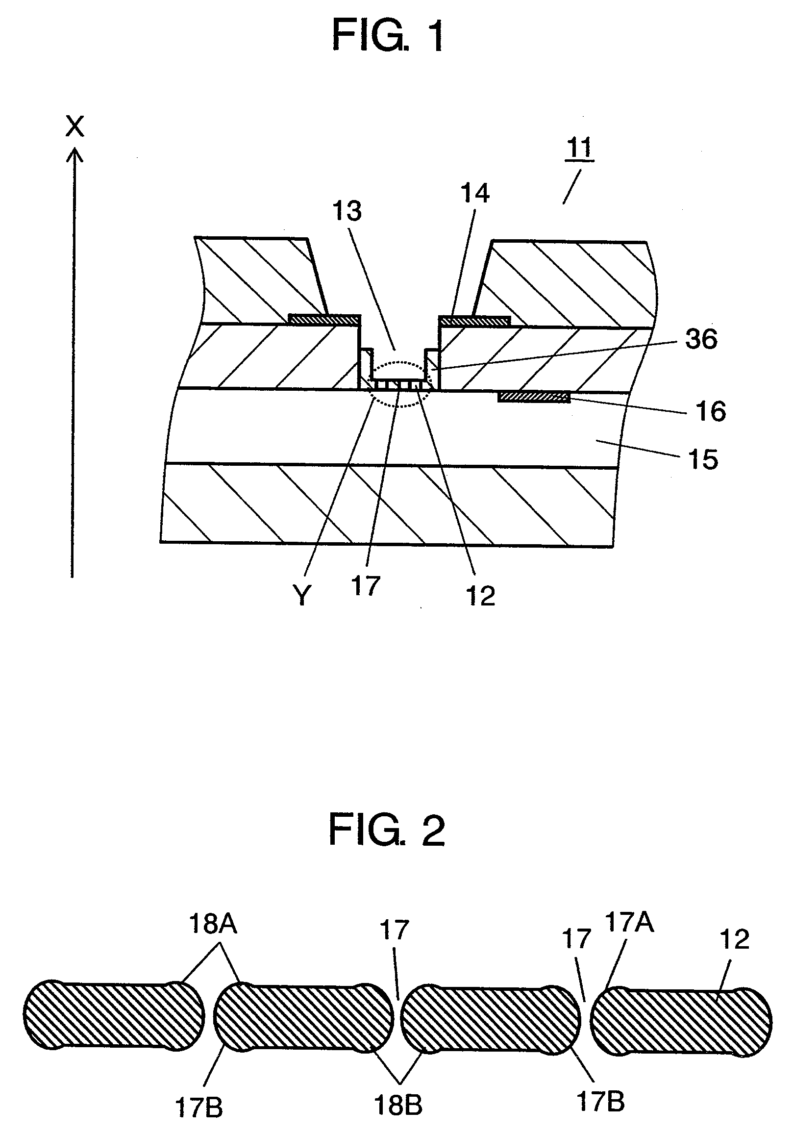
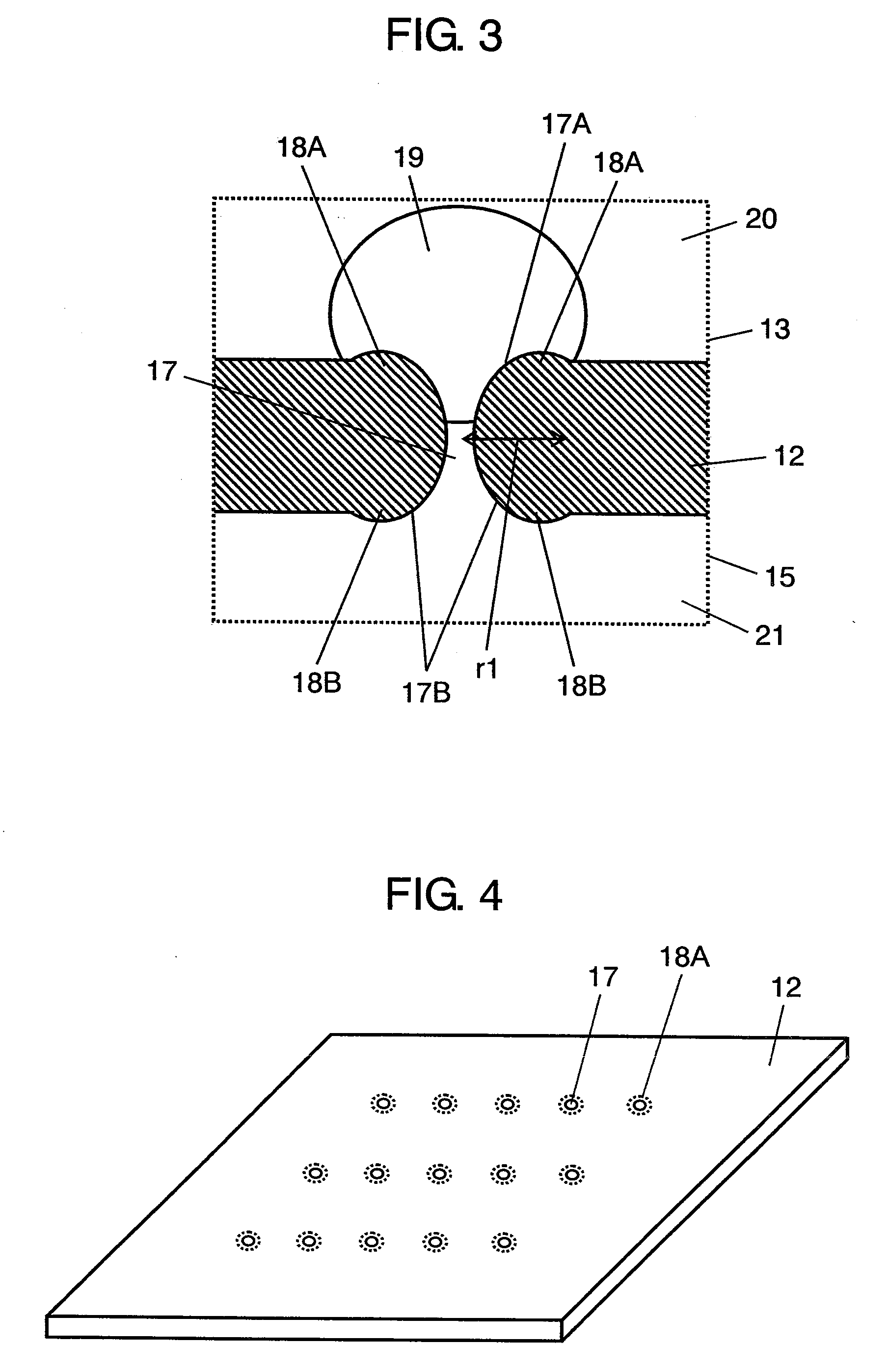
[0071]A cell electrophysiological sensor in preferred embodiment 1 of the invention is described while referring to the drawings. FIG. 1 is a sectional view of cell electrophysiological sensor in preferred embodiment 1, FIG. 2 is a sectional view of a substrate used therein, FIG. 3 is an essential magnified sectional view of operation of the cell electrophysiological sensor, FIG. 4 is a perspective view of the substrate.

[0072]In the preferred embodiments explained below, the upper direction refers to the direction of arrow X in FIG. 1.

[0073]As shown in FIG. 1, the cell electrophysiological sensor 11 in preferred embodiment 1 includes a chip 36 having a substrate 12, a first electrode jar 13 disposed above the substrate 12, a first electrode 14 disposed inside of the first electrode jar 13 and on the upside of the substrate 12, a second electrode jar 15 disposed beneath the substrate 12, and a second electrode 16 disposed inside of the second electrode jar 15 an...

embodiment 2

Preferred Embodiment 2

[0128]A cell electrophysiological sensor in preferred embodiment 2 of the invention is described while referring to the drawing. FIG. 11 is a sectional view of a substrate of cell electrophysiological sensor in preferred embodiment 2.

[0129]The configuration of the substrate 12 used in the cell electrophysiological sensor in preferred embodiment 2 is as shown in FIG. 11, in which the both sides of the substrate 12 and the inner wall surface of the through-hole 17 are covered with an insulating layer 24.

[0130]In such configuration, when the sample cell 19 is held tightly at the opening 17A of the through-hole 17, the first electrode jar 13 and second electrode jar 15 are completely isolated electrically except for the passage to the sample cell 19.

[0131]As the insulating film 24, when a hydrophilic material is used such as silicon oxide or silicon nitride, since the sample cell 19 also has a hydrophilic surface containing hydroxyl group, the sample cell 19 can be...

embodiment 3

Preferred Embodiment 3

[0134]Preferred embodiment 3 differs from preferred embodiment 1 in that a silicon oxide layer is laminated as oxide layer 25 preliminarily at one side of the substrate 12 as shown in a sectional view of a chip 36 shown in FIG. 12.

[0135]In preferred embodiment 3, as shown in FIG. 13, in a block 27 in which the oxide layer 25 is enclosed with a silicon layer 26, a resist mask 28 having a hole is formed, and as shown in FIG. 14, a through-hole 17 is formed by etching from the side of the silicon layer 26 of the substrate 12. In FIG. 13 and FIG. 14, the upper silicon layer 26 of two silicon layers 26 becomes the substrate 12 as shown in FIG. 12.

[0136]At this time, since the oxide layer 25 (silicon oxide) is lower in etching rate than the silicon layer 26, by etching from the silicon layer 26, etching stops at the oxide layer 25, and the depth of the through-hole 17 and thickness of the substrate 12 (substrate 12 in FIG. 12) can be managed at high precision.

[0137]C...


PUM

PropertyMeasurementUnit
temperatureaaaaaaaaaa
diameteraaaaaaaaaa
sizeaaaaaaaaaa

Abstract

A chip for a cell electrophysiological sensor has a substrate. The substrate has a through-hole formed from the upside to the downside, and the opening of the through-hole is formed in a curved surface curved from the upside and downside of the substrate toward the inner side of the through-hole. In this configuration, the electrolyte solution (first electrolyte solution and second electrolyte solution) flows more smoothly, and the sample cell can be sucked accurately, and the trapping rate of the sample cells is improved.

Description

TECHNICAL FIELD[0001]The present invention relates to a chip used in cell electrophysiological sensor for measuring electrophysiological activities of cells, a cell electrophysiological sensor using this chip, and a manufacturing method of chip for cell electrophysiological sensor.BACKGROUND ART[0002]As a method of measuring ion channels depending on cell membrane electrophysiologically, a substrate type probe making use of ultrafine processing technology has been noticed. Unlike the conventional micropipette, it does not require skilled operation for inserting a micropipette into individual cells, and it is suited to an automated system of high throughput.[0003]For example, as shown in FIG. 26, the existing cell electrophysiological sensor 1 (substrate probe) includes a substrate 2 and an electrode jar 3 disposed above the substrate 2. The substrate 2 has a through-hole 5 penetrating through the substrate 2 from its upside to downside.[0004]Inside of the electrode jar 3, a first el...

Claims


Application Information

Patent Timeline
Patent Type & Authority Applications(United States)
IPC IPC(8): G01N27/327H01L21/306
CPCG01N33/48728
Inventor HIRAOKA, SOICHIRONAKATANI, MASAYAUSHIO, HIROSHIOSHIMA, AKIYOSHI
Owner PANASONIC CORP
Learn More