Reaction vessel assembly with gas exchange means

a technology of gas exchange and reaction vessel, which is applied in the direction of lighting and heating apparatus, heating types, and separation processes, etc., can solve the problems of limited atmospheric gas exchange or ventilation, limited atmospheric exchange between the headspace of the flask and the ambient incubator gas, and achieve enhanced convective gassing flow and mixing power drawn

Active Publication Date: 2009-06-18
MOU DUEN GANG
View PDF7 Cites 42 Cited by
  • Summary
  • Abstract
  • Description
  • Claims
  • Application Information

AI Technical Summary

Benefits of technology

[0010]In still another aspect of the present invention, inside the reaction chamber the vessel can have one or more baffle plates to aid the mixing power drawn and the pumping or entrapment of gas into liquid.
[0011]The gas so entrapped in the reaction fluid inside the reaction chamber is vented, in one aspect of the present invention, through the interconnecting gas venting compartment and its opening to the ambient. The gas venting compartment, shielded from the bulk fluid mixing motion in the interconnecting gas intake compartment, works like a gas-lift riser tube or column and allows entrapped gas bubbles entering from the tube's submerged end to vent by floatation force to vessel ambient thru the other end. This steady but significant convective gas vent or out-flow creates a negative pressure differential between the interconnecting gas intake compartment and vessel ambient. This negative pressure differential in turn results in more fresh convective gas intake from vessel ...

Problems solved by technology

One well known drawback of shaken flask (often conical Erlenmeyer flasks) is its limited atmospheric gas exchange or ventilation when reaction must be shielded from the ambient to avoid contamination, notably the use of cotton or sponge plug or gauze/cotton/gauze “sandwiched” layers for closuring from air-born contaminants when culturing things like microbes.
Here, atmospheric exchange between flask headspace and ambient incubator gas is limited to natural convection or diffusion resulting from concentration gradient across the porou...

Method used


Image

  • Reaction vessel assembly with gas exchange means
  • Reaction vessel assembly with gas exchange means
  • Reaction vessel assembly with gas exchange means

Examples


example

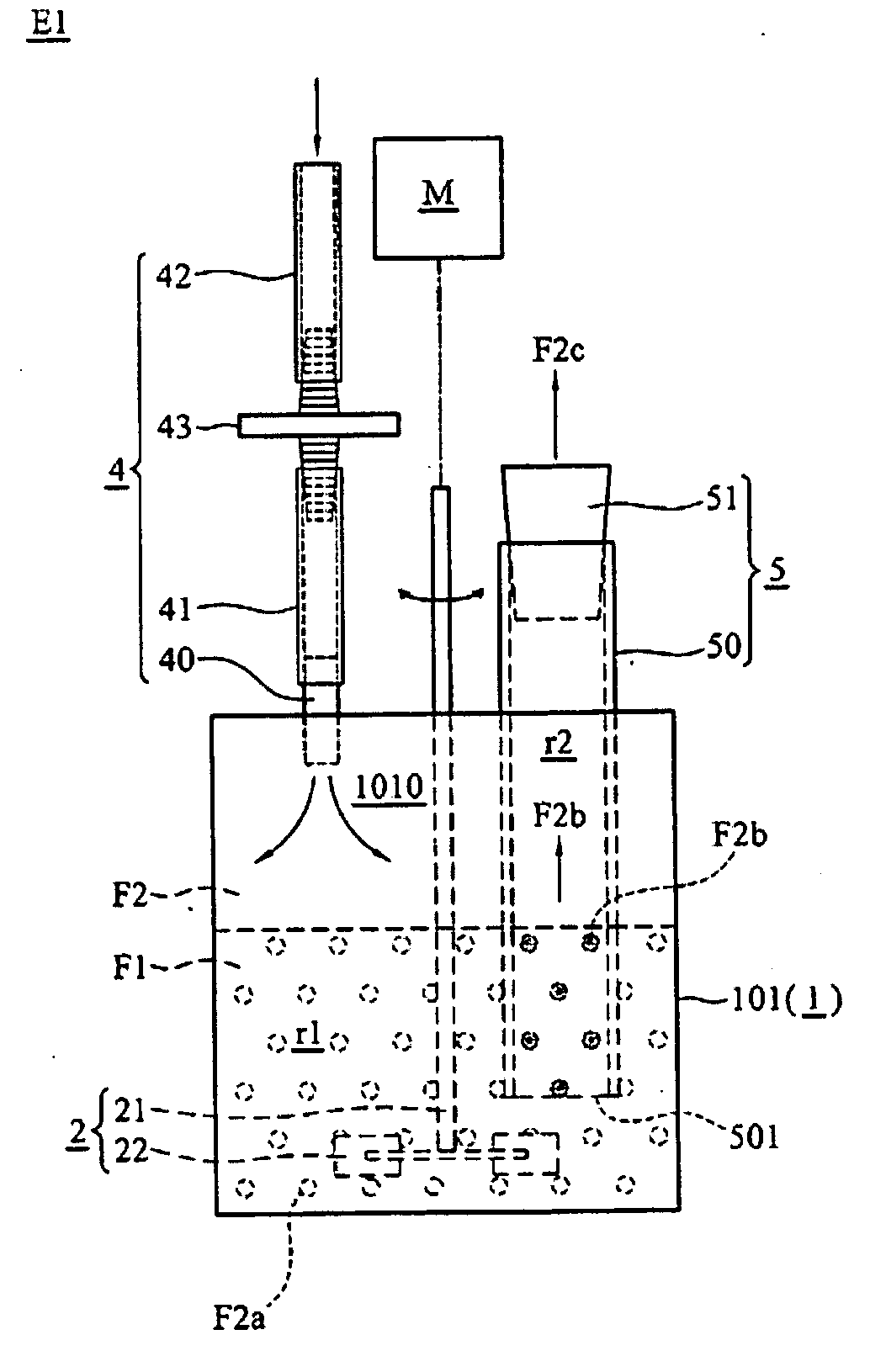
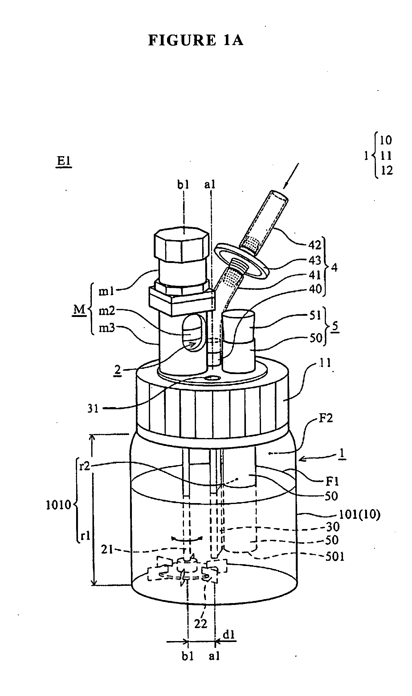
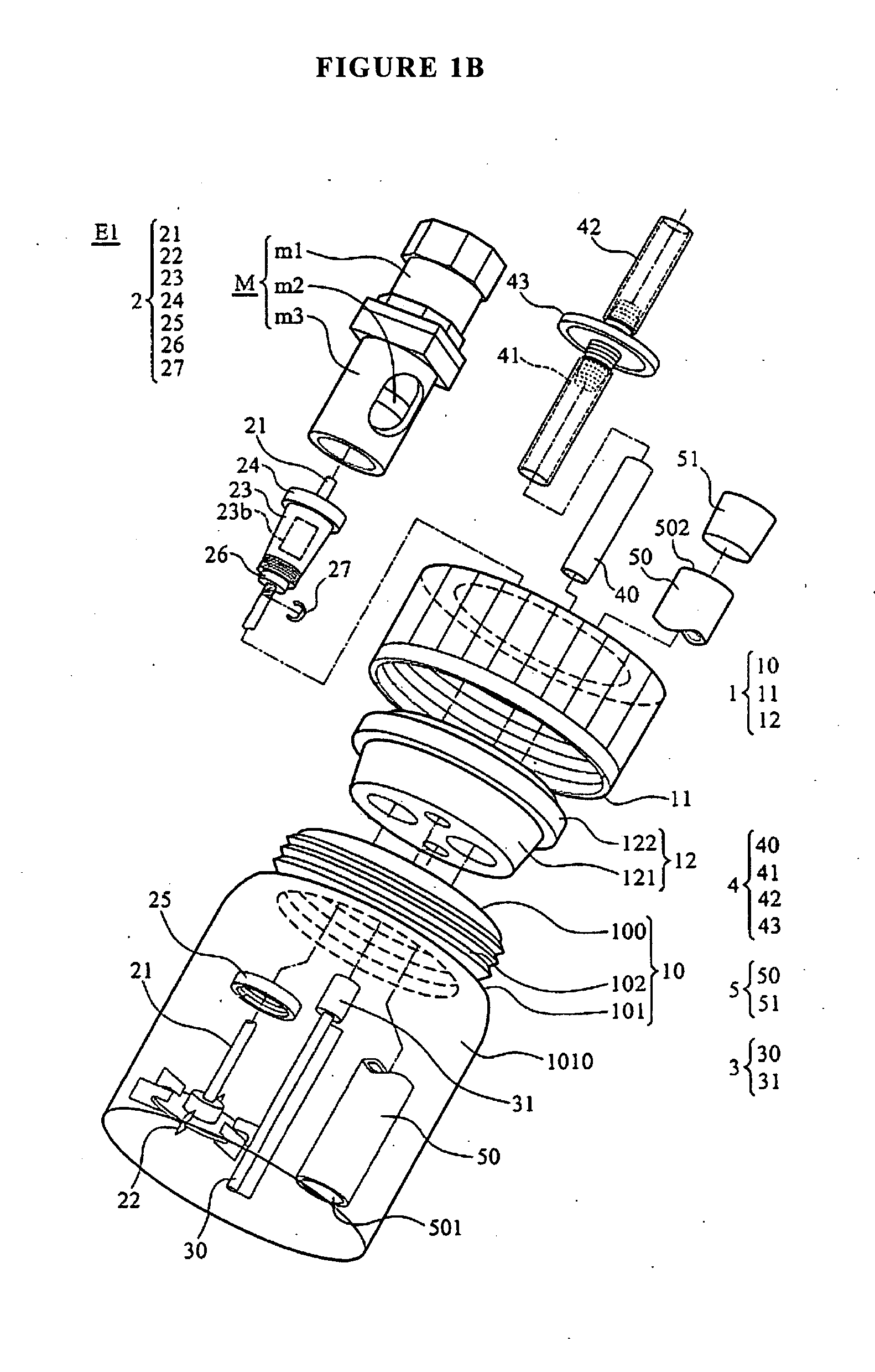
[0042]Dimensions of a 500 ml Schott Duran GLS80 reaction vessel assembly E1′ in FIG. 6 are the following: the gas inlet port insert 40 and the thermometer well 9's OD and ID, respectively, 8 and 6 mm; the gas-lift venting tube 50's OD and ID, respectively, 20 and 17 mm; 6-blade impeller 22's diameter and height, respectively, 38 and 10 mm; tap water volume in reaction chamber 1010 400 ml. The liquid phase F1 is 58 mm in depth, the submersion depth of thermometer well 9, the gas-lift venting tube 50 and the impeller 22 are, respectively, 42, 22 and 32 mm. To make a blow-hole for soap bubble 50b blowing measurement, a rubber material 16 mm serum tube plug 51′ was pulled inside out and the plug end bored open and placed on top of the opening of the gas-lift venting tube 50. This produces an 8.5 mm ID blowhole for the soap bubble blowing experiment and is used to measure the gas vent flux by timing and measuring the bursting height or diameter of the soap bubble 50b from a finger smear ...


PUM


Abstract

A reaction vessel assembly achieves enhanced aeration or gas exchange in its gas-in-liquid multiphase mixing reaction through the use of its mixing energy and gas-lift venting, and without the traditionally practiced external line gas sparging. It combines the best of both shake flask and stirred tank reactor vessel and possesses some of the key generic features like cost and parallel experiment advantages of the traditional flasks and shaker hybrid but without their shortcomings like limited gas exchange and uncharacteristic mixing.

Description

BACKGROUND OF THE INVENTION[0001]Incubating shakers are used to serve reaction flasks and their content in providing desired temperature, stirring, mixing and resulting gas-to-liquid mass transfer through either rotary or reciprocating shaking motion for nearly half a century. Both have throw motions normally in range of 12.5 to 50 mm, i.e., 0.5-2 in, the maximum linear distance moved by any point in and on the flask. Reciprocation is usually about 100 cycles / min and in rotary shaking the range is about 150 to 300 rev / min (Pirt, 1975). The mechanical drive and shaft mechanism causes the shaker table and flask vessels clamped on to the table to gyrate, orbit or move thereby causing the shaker table and flask vessels to shake. When used in microbial fermentation industry, for example, the objectives are usually two folds. One is to provide the key link in translating laboratory culture data to commercial scale operation, i.e., scale up; and the other in scaling down environmental cond...

Claims


Application Information

Patent Timeline
IPC IPC(8): B01F3/04
CPCB01F7/1625B01F13/1013B01F13/1022C12M23/08C12M37/02C12M27/16C12M27/20C12M29/20C12M27/02B01F27/81B01F33/81B01F33/813
Inventor MOU, DUEN GANG
Owner MOU DUEN GANG
Why Eureka
Try Eureka