Particle display with jet-printed color filters and surface coatings

a color filter and surface coating technology, applied in the manufacture of electrode systems, electric discharge tubes/lamps, instruments, etc., can solve the problems of increasing process complexity, reducing the range of colors, and the display material does not control the color

Inactive Publication Date: 2009-06-18
PALO ALTO RES CENT INC
View PDF12 Cites 68 Cited by
  • Summary
  • Abstract
  • Description
  • Claims
  • Application Information

AI Technical Summary

Benefits of technology

[0001]Particle based displays, such as electrophoretic displays, magnetophoretic displays and powder displays often contain a display material that absorbs or reflects light depending on an applied electric or magnetic field. However, the display material does not control color. Instead, color filters positioned adjacent the display material are used to achieve a broad spectrum of colors. The technique is analogous to that used in liquid crystal displays. In liquid crystal displays the liquid crystal material controls light transmission through color filters formed adjacent to the black matrix. The black matrix prevents light leakage between the different colour pixel areas.

Problems solved by technology

However, the display material does not control color.
Forming color filters over the display represents a challenge.
However the described photolithographic methods are complex.
Process complexity increases costs and reduces process reliability.
Some electrophoretic materials are not easily dyed.

Method used


Image

  • Particle display with jet-printed color filters and surface coatings
  • Particle display with jet-printed color filters and surface coatings
  • Particle display with jet-printed color filters and surface coatings

Examples


Embodiment Construction

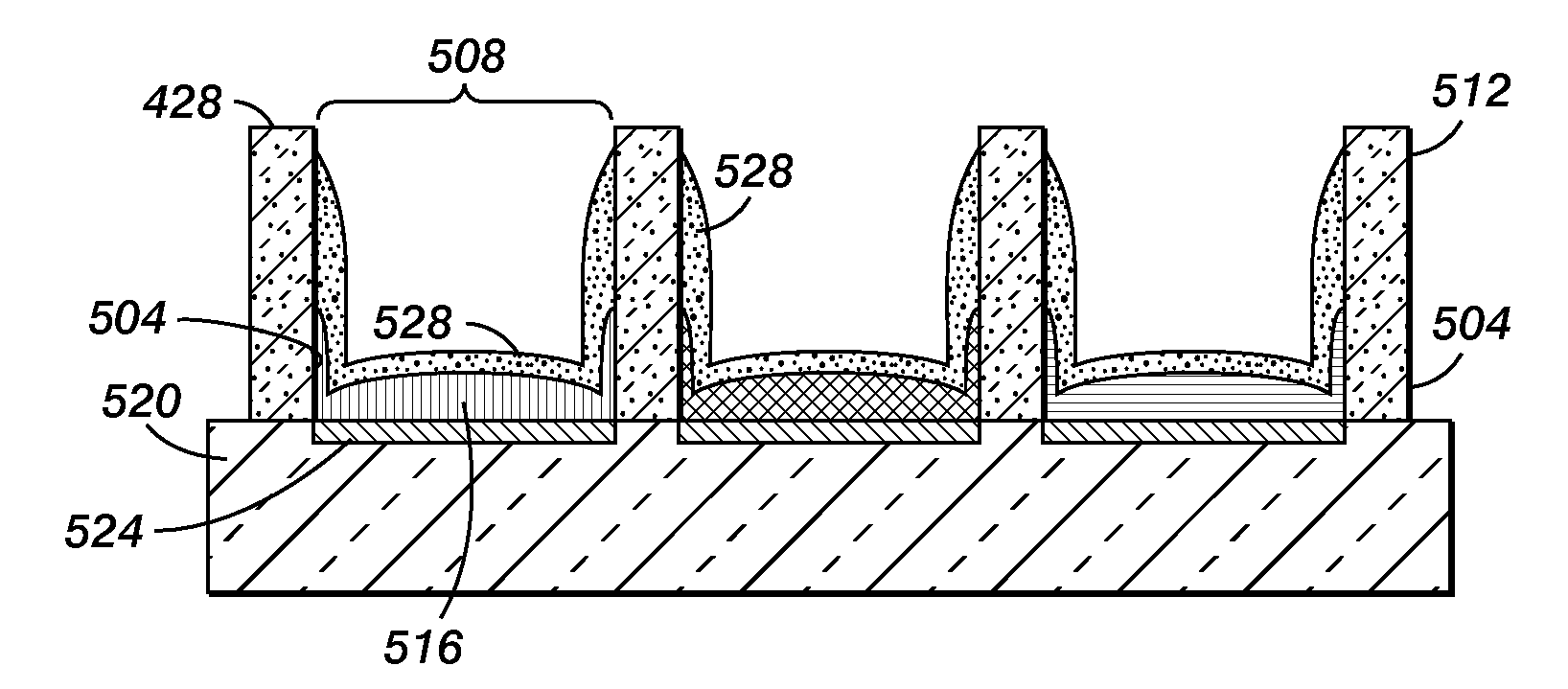
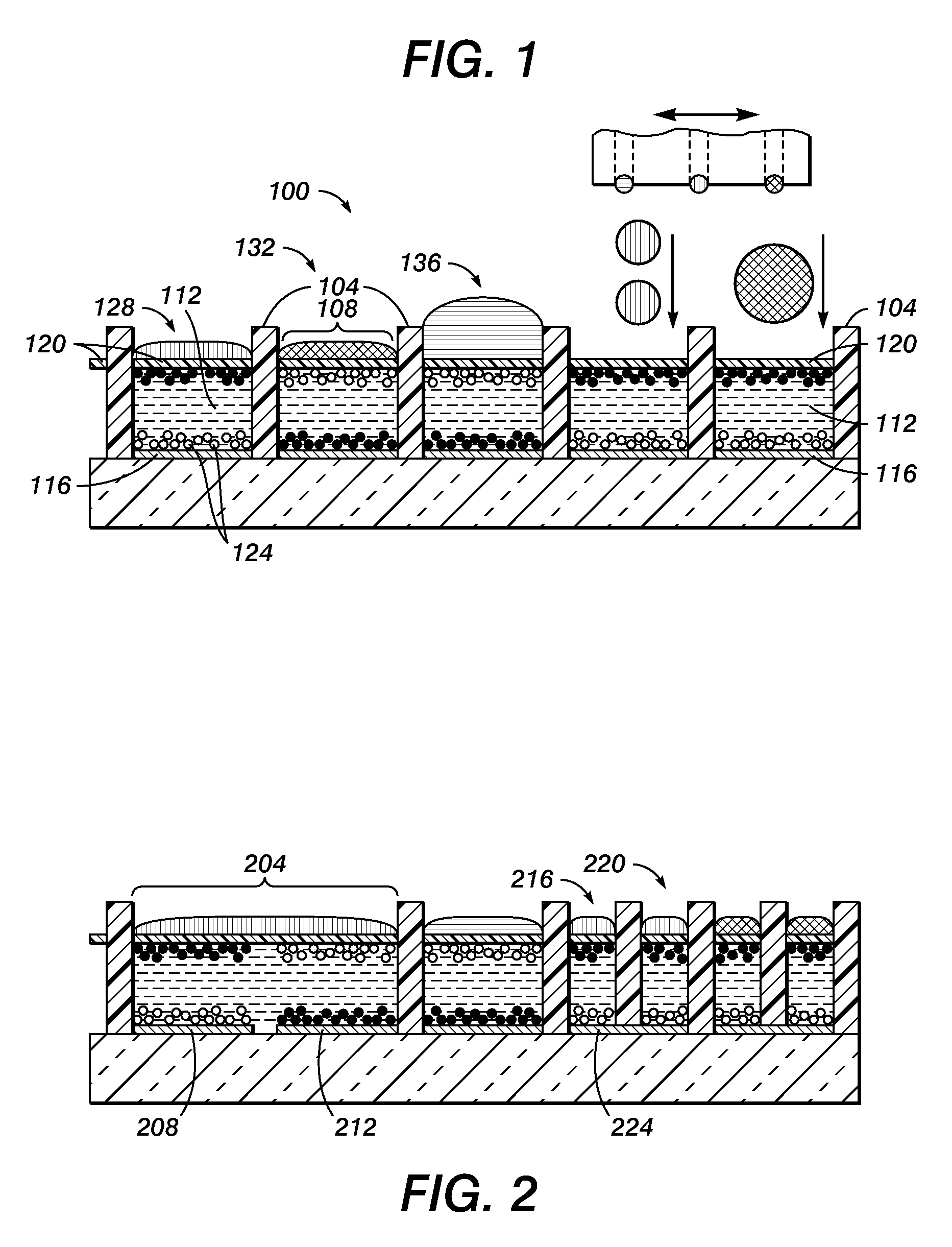
[0011]Typical displays, particularly particle displays, utilize an array of cell structures that confine a display material. The design described herein takes advantage of the cell structure walls that confine the display material to also confine a color filter material. In one deposition technique, the filter material is jet printed into the cells of the structure, although other deposition techniques may be used. The use of the same walls to confine both the particles / particle suspension and the filter material greatly facilitates device fabrication.

[0012]FIG. 1 shows one example of a cell structure 100 that includes cell walls 104 confining a display material 112. As used herein, “display material” is broadly defined to include any material that changes light transmissivity or reflectivity based on an applied electrical or magnetic field. Display material may also include materials that change state due to applied heat or due to an electrochemical reaction. In one embodiment, the...


PUM

PropertyMeasurementUnit
heightsaaaaaaaaaa
heightsaaaaaaaaaa
heightsaaaaaaaaaa

Abstract

An improved method of forming a display is described. The method includes the operation of forming a cell in an array of cells. Walls of the cell are used to confine both a color filter and a display material prior to sealing the cell. The method is particularly useful when jet printing particulate display materials and filter materials to form pixels in a display.

Description

BACKGROUND AND SUMMARY[0001]Particle based displays, such as electrophoretic displays, magnetophoretic displays and powder displays often contain a display material that absorbs or reflects light depending on an applied electric or magnetic field. However, the display material does not control color. Instead, color filters positioned adjacent the display material are used to achieve a broad spectrum of colors. The technique is analogous to that used in liquid crystal displays. In liquid crystal displays the liquid crystal material controls light transmission through color filters formed adjacent to the black matrix. The black matrix prevents light leakage between the different colour pixel areas.[0002]Forming color filters over the display represents a challenge. U.S. Patent Appl. US2002 / 0196525A1 filed Dec. 26, 2002 entitled “Process for Imagewise Opening and Filling Color Display Components and Color Displays Manufactured Thereof” by Xianhai Chen et al describes using photolithogr...

Claims


Application Information

Patent Timeline
Patent Type & Authority Applications(United States)
IPC IPC(8): G02B26/00H01J9/26G02F1/167G02F1/1677
CPCG02F1/133516G02F2001/1672G02F1/167G02F1/13394G02F1/1681G02F1/1677
Inventor DANIEL, JURGEN H.READY, STEVEN E.
Owner PALO ALTO RES CENT INC
Why Eureka
Try Eureka