
Battery energy storage system with arc flash protection, energy conversion system and protection method

a technology of energy conversion system and battery energy storage system, which is applied in the direction of secondary cells, battery service/maintenance, safety/protection circuit, etc., can solve the problems of low battery voltage level, damage to the battery system or adjacent devices, and jeopardize the health and life of people, so as to reduce the risk of system components and people, avoid potential fire damage, and reduce the effect of fault detection and fault shut-down

Active Publication Date: 2015-08-27
GE ENERGY POWER CONVERSION TECH
View PDF2 Cites 31 Cited by
  • Summary
  • Abstract
  • Description
  • Claims
  • Application Information

AI Technical Summary

Benefits of technology

The invention is a device that combines overcurrent protection and undervoltage protection to detect and prevent different short circuit conditions and fault currents in a battery system. It can detect short-circuit currents and low battery voltage levels and can trigger suitable protection devices to prevent even long-lasting arc flashes that could damage the battery system or adjacent devices and jeopardize the health and life of people. The device can be easily installed and retrofitted into existing battery management systems and can also be connected to a timer to detect and initiate protective counter-measures when specific conditions are met. Overall, the device provides a safe and reliable operation of battery energy storage systems and can be used in all types of battery applications.

Problems solved by technology

In addition, the arc flash protection device detects unusually low voltage levels of the battery voltage.
These might otherwise not be detected by the overcurrent protection device and result in the damage of the battery system or adjacent devices, and jeopardize the health and life of people.

Method used


Image

  • Battery energy storage system with arc flash protection, energy conversion system and protection method
  • Battery energy storage system with arc flash protection, energy conversion system and protection method
  • Battery energy storage system with arc flash protection, energy conversion system and protection method

Examples


Embodiment Construction

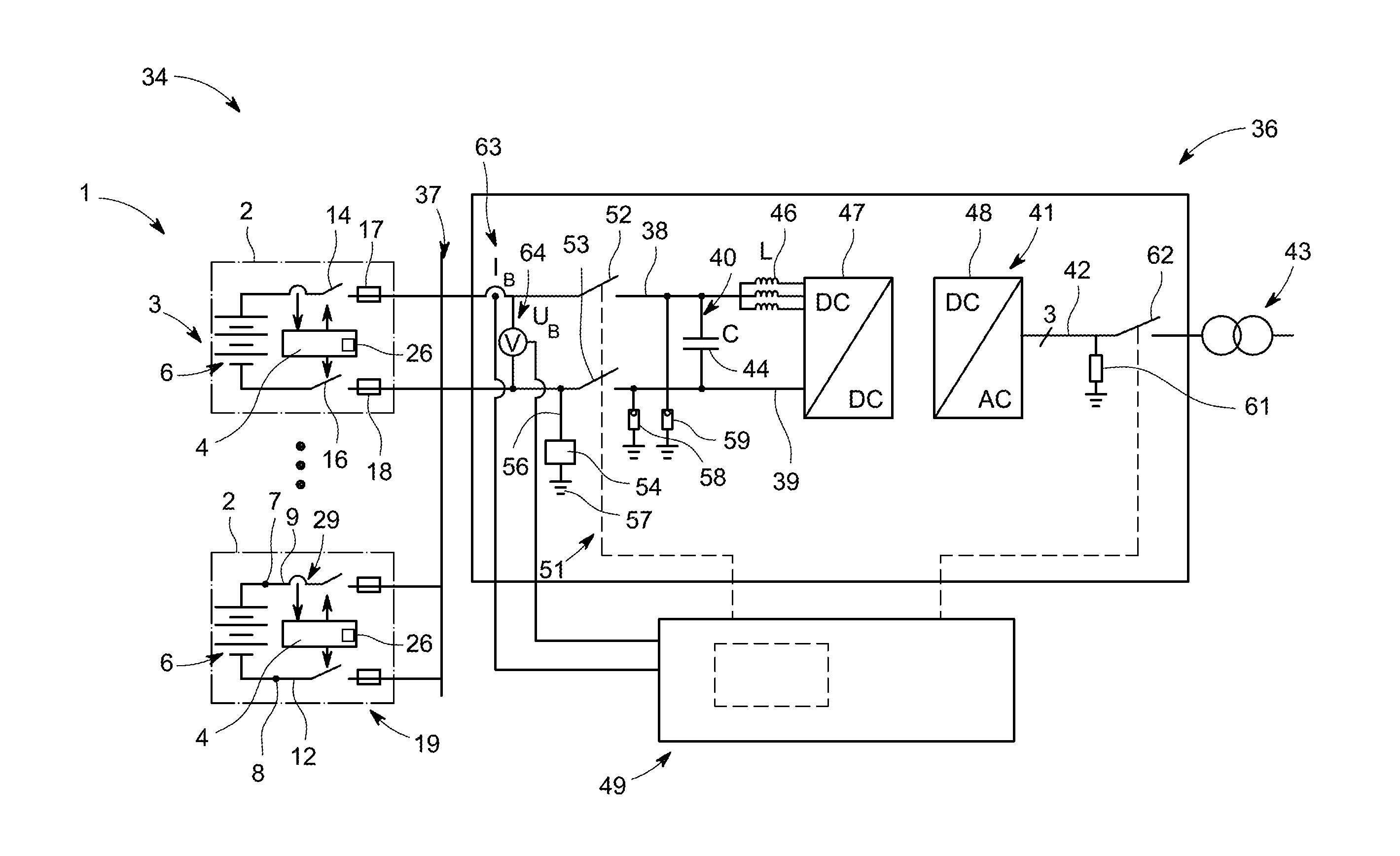
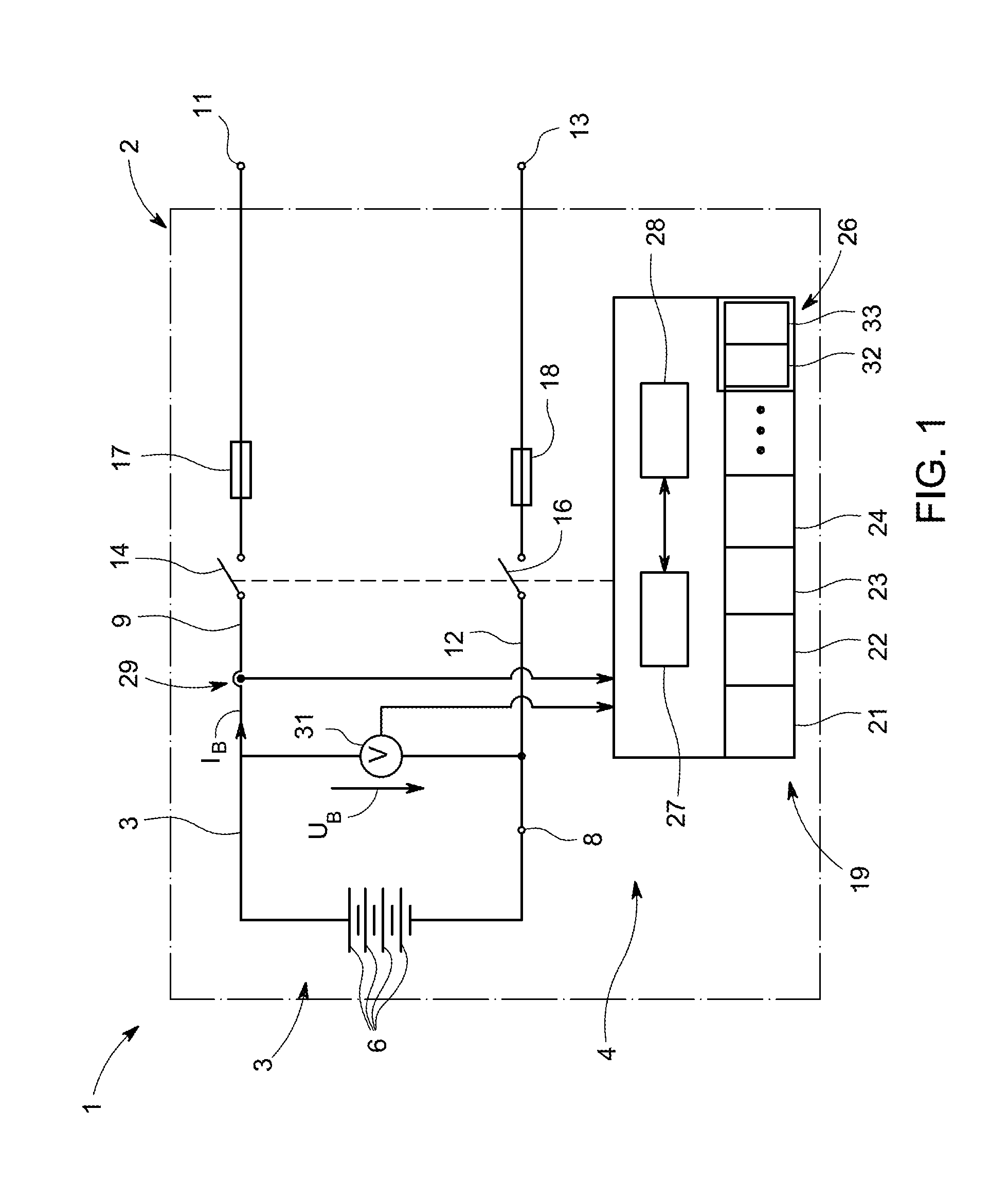
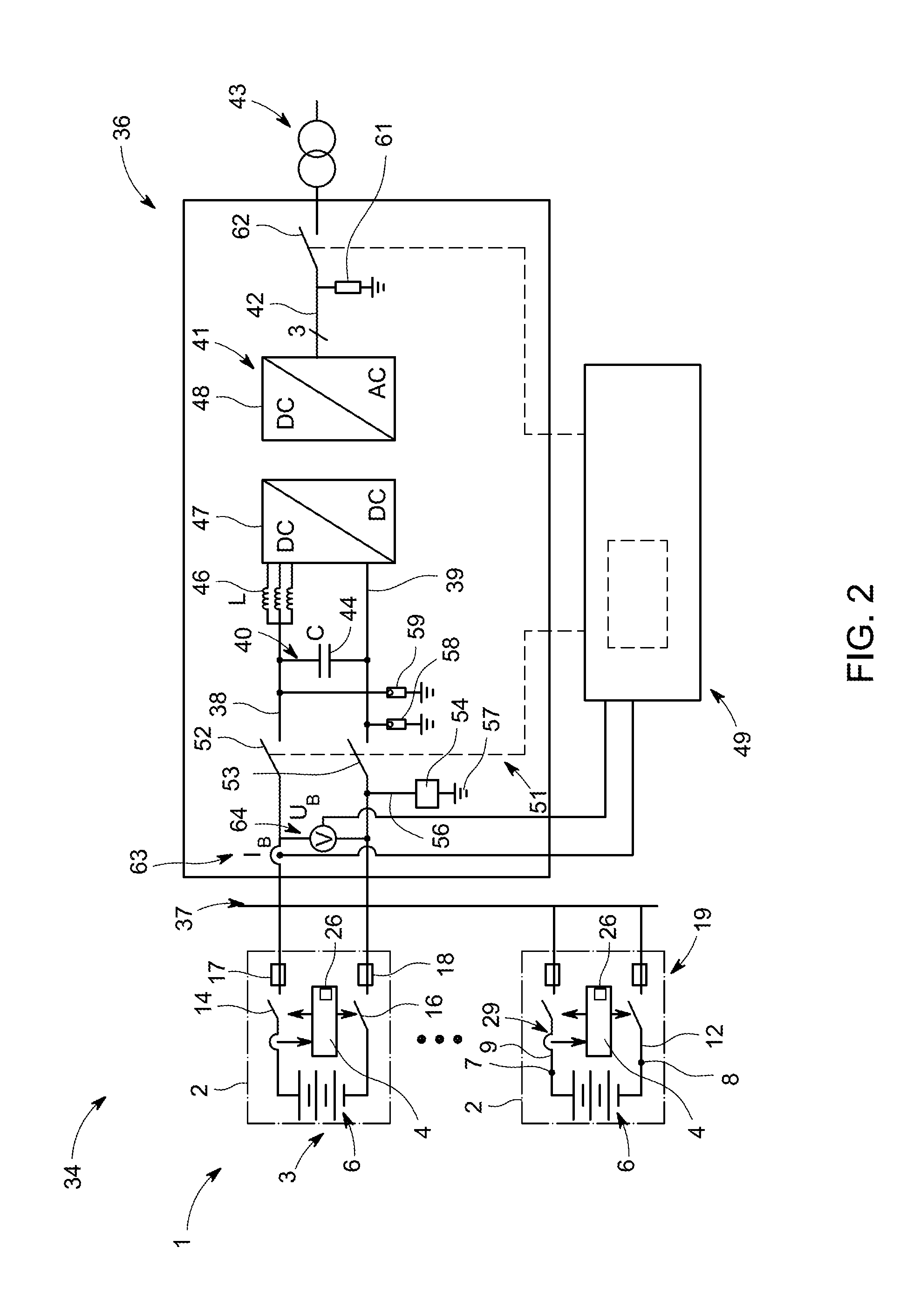
[0039]FIG. 1 shows a greatly simplified block circuit diagram of a battery energy storage system 1 in accordance with one embodiment of the invention that, here, is formed by a single battery module 2 that comprises, in a shared housing (not illustrated), a rechargeable battery assembly 3 for the storage and provision of energy, including all associate connections and associate electronics, including a battery management system 4 for monitoring and controlling the rechargeable battery assembly 3.

[0040]The battery assembly 3 comprises several series-connected battery cells 6, each exhibiting a DC voltage of, e.g., 12, 24 or 48 Volt, in which case, due to the series connection of the cells, any desirable nominal DC voltage of the battery assembly 3 can be achieved. In an application of the battery energy storage system 1 for battery energy storage power plants, the battery assembly 3 is designed for a nominal DC voltage of at least 450 Volt to approximately 600 Volt, or even higher.

[0...


PUM


Abstract

A battery energy storage system is disclosed, the battery energy storage system comprising a rechargeable battery assembly for storing and providing energy and a protection system including an arc flash protection device to protect against risks due to arc flashes. The arc flash protection device comprises an overcurrent protection unit which detects overcurrent conditions indicating arc flash conditions in case of a low impedance of the battery assembly and an undervoltage protection unit which detects undervoltage conditions indicating arc flash conditions in case of a low impedance of the battery assembly, wherein upon detecting the overcurrent conditions and / or the undervoltage conditions for a predetermined minimum time period, the arc flash protection device initiates protective measures to prevent further operation of the battery assembly. An energy conversion system comprising such a battery energy storage system, which can be used for stationary and mobile energy supply or distribution applications, is also disclosed.

Description

FIELD OF THE INVENTION[0001]The present invention relates to the field of battery energy storage systems and to energy systems with battery energy storage systems, in general, and to a battery energy storage system comprising an arc flash protection device, an energy conversion system with such a battery energy storage system, in particular, and to a method for the protection of these.[0002]Increasingly, battery energy storage systems are used in many mobile and stationary applications. For example, battery energy storage systems are used in conjunction with energy supply and energy distribution systems in networks that use a share of renewable energy sources. Battery energy storages allow the balancing of energy supplies that fluctuate on account of renewable energy sources, the improvement of net stability and net quality by peak smoothing and load balancing, the shifting of renewable photovoltaic energy from day to night and / or of wind energy to low-wind times, and thus allow a r...

Claims


Application Information

Patent Timeline
IPC IPC(8): H02H3/38H01M10/48H02H7/18H01M10/42
CPCH02H3/38H01M10/425H01M10/48H01M2220/20H01M2010/4271H01M2220/10H02H7/18H02H1/0015H02H3/087H02H3/093H02J1/108H02J7/00718H02J7/00304H02J7/0013Y02E60/10H02J7/00302H02J7/00306H02J7/00309
Inventor ROESNER, ROBERTRYTZ, CHRISTOPH
Owner GE ENERGY POWER CONVERSION TECH
Learn More