
Drilling tool, in particular for metallic materials

Inactive Publication Date: 2009-06-18
AUDI AG
View PDF16 Cites 2 Cited by
  • Summary
  • Abstract
  • Description
  • Claims
  • Application Information

AI Technical Summary

Benefits of technology

[0009]According to the invention, the resulting shavings are thus pressed as a result of the acting centrifugal forces into the groove which can extend preferably in a straight line, without coiling, in the longitudinal direction of the drill body. This straight groove promotes prompt discharge of shavings.
[0011]According to another embodiment, the web can alternatively project over the top of the cutting element, as a result of which accordingly the groove height can be easily raised. In this connection the bottom of the groove formed between the web and the opposite side wall of the chip space can end essentially flush with the top of the cutting element. In order to support the transport of shavings from the face-side cutting element out of the chip space, the depth of the groove formed between the web and the opposite side wall of the chip space can be increased in the direction of the clamping shaft.
[0013]The conveyance of the shavings through the chip space is further promoted when the side walls of the chip space are made planar and / or are arranged essentially at a right angle to one another. Preferably the groove formed between the web and the opposite side wall of the drill body can be laterally opened on the shaft side with an outlet in order to enable conveyance of the shavings out of the chip space.
[0017]To supply the drilling tool with coolant, the drilling tool can have at least one central coolant line, from which a first and a second coolant channel branch off. Alternatively the central coolant line can be flow-connected by way of a transverse hole to the first and the second coolant channel. In this case, the first coolant channel can discharge as a main channel with a larger flow cross section into the side wall of the chip space which is opposite the web. The second coolant channel can discharge as a secondary channel with a smaller flow cross section into the side wall which bears the cutting element. The arrangement of the second coolant channel underneath the cutting element can further support discharge of the shavings and bunching of the shavings in the apex area.
[0018]The flow velocity of the coolant emerging from the channels in the longitudinal direction of the drill body depends on the volumetric flow and on the exit diameter of the coolant channels. An additional coolant velocity component is produced by the centrifugal force when the drilling tool is rotating. The light flow velocity of the coolant leads to a low static pressure of the coolant, resulting in the production of a suction action in the chip space. A large dynamic pressure which arises as a result of the high flow velocity causes the coolant to be able to efficiently remove the shavings from the chip space.

Problems solved by technology

This partially helical pattern of the chip spaces and the radially open configuration of the chip spaces adversely affect the discharge of shavings from the drill hole.
Especially in a prefabricated cylinder head hole in whose walls there are cavities such as pockets or transverse holes, this has the disadvantage that shavings stick in the cavities.

Method used


Image

  • Drilling tool, in particular for metallic materials
  • Drilling tool, in particular for metallic materials
  • Drilling tool, in particular for metallic materials

Examples


first embodiment

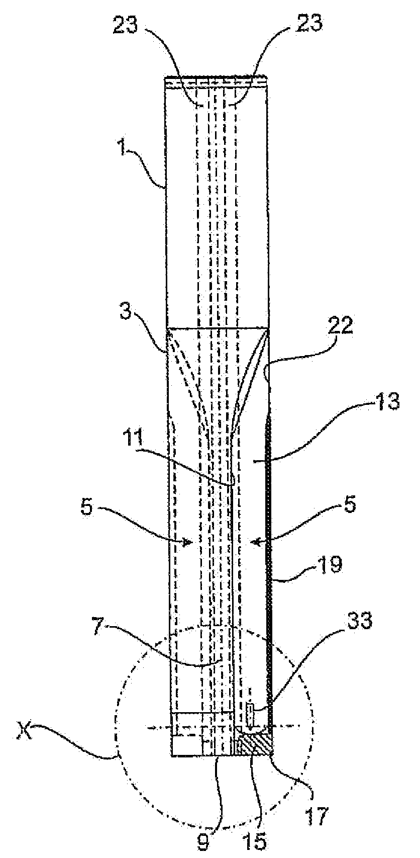
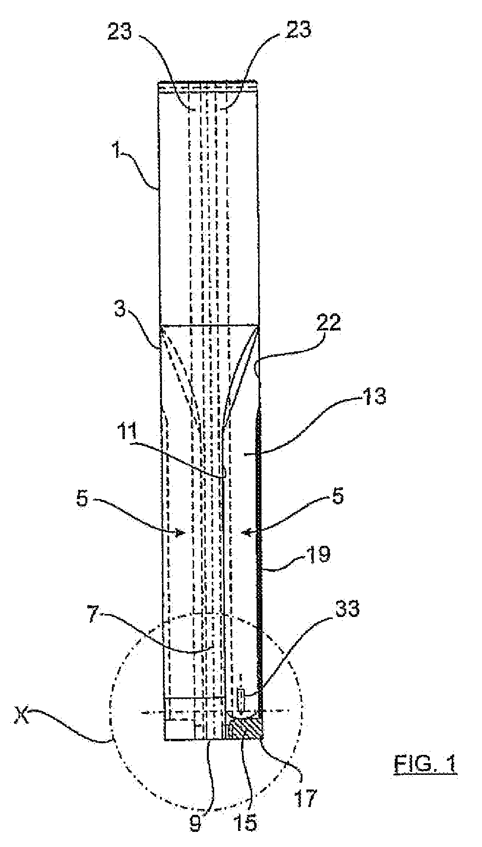
[0027]FIG. 1 shows a drilling tool for drilling in metallic workpieces according to the The drilling tool has a cylindrical clamping shaft 1 which conventionally adjoins the drill body 3. The drill body 3 has two essentially groove-shaped chip spaces 5 which extend to both sides of the longitudinal axis 7 of the drill body and discharge into the face surface 9 of the drill body 3. Each of the chip spaces 5 is bordered by two side walls 11 and 13.

[0028]Of the two side walls 11, 13 of the chip spaces 5, side wall 13 on its face end has a pocket-shaped recess in which a plate-shaped cutting element 15 sits, the top side thereof ending flush with the side wall 13. The cutting element 15 with its face-side cutting edge 17 projects slightly over the face surface 9 of the drill body 3 and radially protrudes slightly over the periphery of the drill body, as is indicated in FIG. 3.

[0029]FIG. 2 shows the face surface 9 of the drill body 3 in a front view with the two opposite chip spaces 5. ...

second embodiment

[0040]This yields a groove depth which has been increased compared to the first and second embodiment, as a result of which the resulting shavings can be discharged even more reliably from the drill hole in the groove 21, and therefore without contact relative to the drill wall.


PUM

PropertyMeasurementUnit
Timeaaaaaaaaaa
Pressureaaaaaaaaaa
Angleaaaaaaaaaa

Abstract

The invention relates to a drilling tool, in particular for metallic materials, having a clamping shaft and an essentially cylindrical drill body, between whose face side and the clamping shaft at least one groove-shaped chip space extends which is bordered by the side walls, of which one side wall on the face side of the drill body bears a cutting element. The side wall which bears the cutting element has a web which is drawn up from the side wall in the peripheral direction and which extends in the longitudinal direction of the drill.

Description

[0001]The invention relates to a drilling tool, in particular for metallic materials.BACKGROUND OF THE INVENTION[0002]These drilling tools are used in automotive engineering, for example in the production of cylinder head holes, for drilling out of a solid material or for enlarging already prefabricated drill holes.[0003]Thus EP 0 750 960 B1 discloses a generic drilling tool which has a conventional clamping shaft and an adjoining cylindrical drill body. Between the face side of the drill body and the clamping shaft there extend two groove-shaped chip spaces. They are each bordered by side walls, of which one side wall at a time bears a cutting element on the face side of the drill body. Shavings from the drill hole are discharged to the outside in the two chip spaces during the drilling process.[0004]The side wall of the respective chip space, which wall bears the cutting element, is made planar here and ends flush with the top of the cutting element. The two chip spaces extend par...

Claims


Application Information

Patent Timeline
IPC IPC(8): B23B51/06B23B31/10B23B51/00
CPCB23B51/0493Y10T408/9095Y10T408/953Y10T408/455
Inventor KOPTON, PETER
Owner AUDI AG
Features
  • Generate Ideas
  • Intellectual Property
  • Life Sciences
  • Materials
  • Tech Scout
  • Unparalleled Data Quality
  • Higher Quality Content
  • 60% Fewer Hallucinations
Learn More