Fuel cell system and generation control device

a technology of fuel cell and control device, which is applied in the direction of fuel cell control, fuel cells, cell components, etc., can solve the problems of difficult to accurately grasp the water amount and wet condition inside the fuel cell, and achieve the effect of reducing the output of the fuel cell and obstructing power generation

Inactive Publication Date: 2009-06-18
TOYOTA JIDOSHA KK
View PDF3 Cites 16 Cited by
  • Summary
  • Abstract
  • Description
  • Claims
  • Application Information

AI Technical Summary

Benefits of technology

[0024]Generally, with the fuel cell, water is generated on the side of an oxygen electrode (cathode) to which oxidant gas is supplied when power is generated. This water may be liquefied by condensation, and may stagnate in a gas flow passage by bedewing, etc. As a result, if the water cannot be exhausted out of the system, a so-called flooding state where the flow passage of the oxidant gas is blocked is apt to occur. This will obstruct power generation and lower the output of the fuel cell. Further, since the generated water can exude even toward a fuel electrode (anode) through an electrolyte membrane, the flow passage of the fuel gas may be blocked, and thereby, the flooding may occur similarly. Therefore, it is preferable to calculate the amount of water exhausted as a liquid component with respect to both fuel gas and oxidant gas from the viewpoint of contribution to the control for preventing this flooding, and it is preferable to perform such calculation with respect to oxidant gas when such calculation is performed with respect to either the fuel gas or oxidant gas.
[0025]According to such a fuel cell system of the invention, since the water balance in the fuel cell is determined by considering not only the amount of water exhausted as a gas component from the fuel cell but the amount of water exhausted as a liquid component, the water amount inside the fuel cell can be grasped more accurately, and thereby the wet condition inside the fuel cell can be determined more accurately and precisely.

Problems solved by technology

However, in the above conventional fuel cell system, the water that exists and is exhausted as such a liquid component is not considered in calculation of the water balance, and therefore it is difficult to accurately grasp the water amount and wet condition inside the fuel cell.

Method used


Image

  • Fuel cell system and generation control device
  • Fuel cell system and generation control device
  • Fuel cell system and generation control device

Examples


Embodiment Construction

[0030]Hereinafter, embodiments of the invention will be described in detail. In addition, the same reference numerals will be given to the same elements, and the duplicate description will be omitted. Further, the positional relationship, such as up, down, right, and left, shall be based on the positional relationship shown in the drawings, unless otherwise defined. Moreover, the dimensional ratio of the drawings will not be limited to the ratio of illustration.

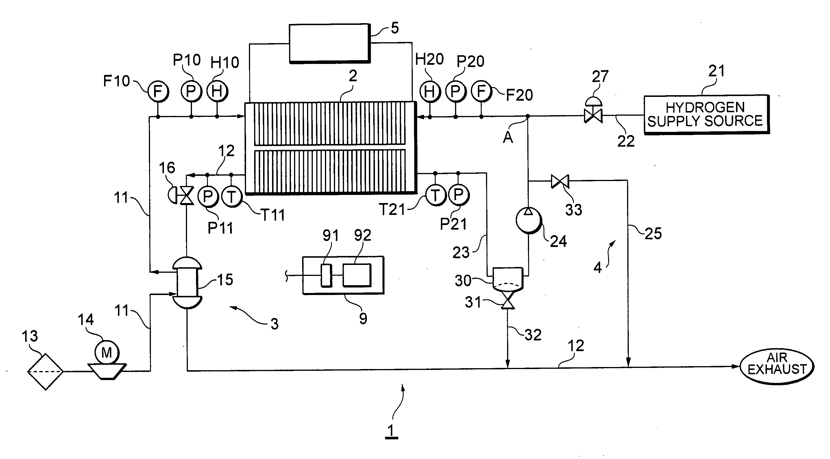
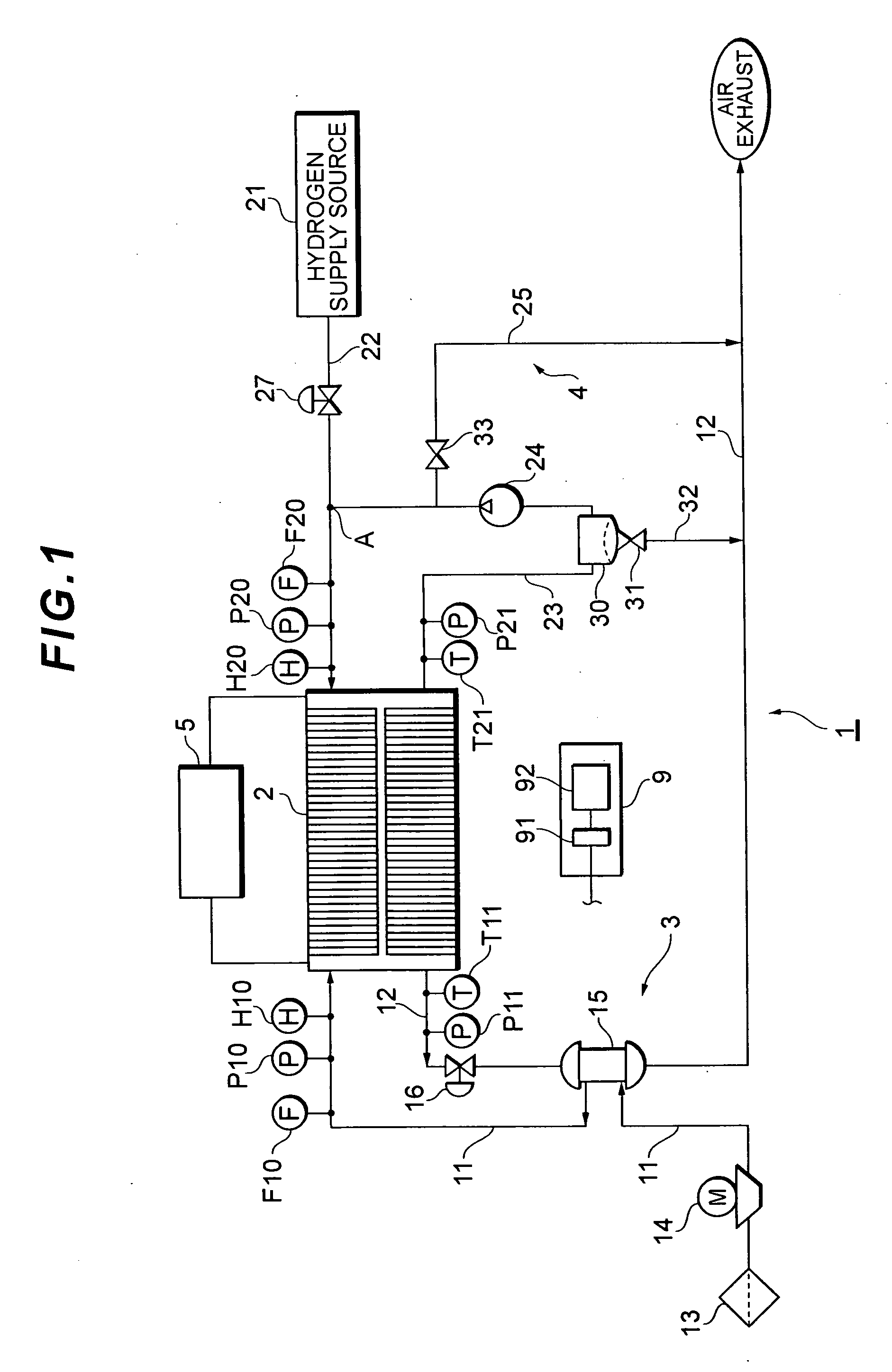
[0031]As described above, FIG. 1 is a block diagram schematically showing one embodiment of a fuel cell system according to the invention. A fuel cell system 1 includes a solid polymer electrolyte type fuel cell 2 that has a stack structure in which a number of cells are stacked. The fuel cell 2 is supplied with air as oxidant gas and hydrogen gas (H2) as fuel gas to generate electric power.

[0032]An air supply system 3, which has a supply pipe 11 for supplying air (inflow gas) to the fuel cell 2 and an exhaust pipe 12 for exh...


PUM

PropertyMeasurementUnit
stack temperatureaaaaaaaaaa
temperatureaaaaaaaaaa

Abstract

A fuel cell system capable of accurately and precisely determining the wet condition inside a fuel cell. The fuel cell system includes a solid polymer electrolyte type fuel cell having a stack structure. The fuel cell is connected to an air supply system, a hydrogen gas supply system, an output system, and a control unit. The control unit receives flow rates of air and hydrogen gas which flow into the fuel cell, their pressures when exhausted, and a generated current measurement signal. The control unit calculates the amounts of water exhausted from the fuel cell as a gas component and as a liquid component and determines the water balance in the fuel cell.

Description

TECHNICAL FIELD[0001]The present invention relates to a fuel cell system and a generation control device.BACKGROUND ART[0002]In a fuel cell system, the fuel gas represented by hydrogen gas and the oxidant gas represented by air are supplied to a fuel cell, and electric power is generated by the generation reaction (water generation reaction) of the fuel gas and the oxidant gas. As the fuel cell, various types of fuel cells have been developed. Among them, a polymer electrolyte fuel cell (PEFC) that has no problems with dissipation or retention of an electrolyte, having advantages that it starts up at room temperature and that warm-up time is extremely short, attracts a special attention. In order to obtain high voltage, stacked PEFCs are adopted in movable bodies such as automobiles.[0003]In this polymer electrolyte fuel cell, a polymer electrolyte layer conducts protons in the reaction between fuel gas and oxidant gas. Therefore, in order to efficiently maintain a generation reacti...

Claims


Application Information

Patent Timeline
Patent Type & Authority Applications(United States)
IPC IPC(8): H01M8/04H01M2/00
CPCH01M8/04119Y02E60/50H01M8/0432H01M8/04328H01M8/04335H01M8/04343H01M8/0435H01M8/04388H01M8/04395H01M8/04402H01M8/0441H01M8/04492H01M8/045H01M8/04507H01M8/04514H01M8/04522H01M8/04589H01M2008/1095H01M8/04156
Inventor ORIHASHI, NOBUYUKI
Owner TOYOTA JIDOSHA KK
Why Eureka
Try Eureka