Biochip for sorting and lysing biological samples

a biochip and biological sample technology, applied in the field of biological device for manipulating biological samples, can solve the problems of unwanted local electrical fields within the microfluidic region, unwanted electrochemical effects of edge effects in uninsulated areas, and unwanted thermal convection exerting unwanted forces on cells,

Inactive Publication Date: 2009-06-18
AGENCY FOR SCI TECH & RES
View PDF5 Cites 43 Cited by
  • Summary
  • Abstract
  • Description
  • Claims
  • Application Information

AI Technical Summary

Benefits of technology

[0017]In accordance with yet another aspect of the present invention, there is provided a method for cell lysing, comprising the steps of: loading a biological sample into a microfluidic channel, wherein the microfluidic channel walls are conductive electrodes; applying a potential difference to the conductive electrodes causing target cells to experience a dielectrophoretic force under an electric field moving the target cells to the tips of the conductive electrodes; and applying a high pulse potential difference to the conductive electrodes causing the target cells to experience electroporation.
[0018]In accordance with yet a further aspect of the present invention, there is provided a method for performing cell sorting and cell lysing on a single device, comprising: loading a biological sample into a microfluidic channel in the device, wherein the microfluidic channel walls are conductive electrodes; applying a potential difference to the conductive electrodes causing target cells to experience a dielectrophoretic force under an electric field; removing unwanted cells from the microfluidic channel using an applied fluidic pressure; applying a potential difference to the conductive electrodes causing the target cells to experience a dielectrophoretic force under an electric field moving the target cells to the tips of the conductive electrodes; and applying a high pulse potential difference to the conductive electrodes causing the target cells to experience electroporation.

Problems solved by technology

As a result of their planar structure, these devices have a number of problems.
Other general problems associated with conventional dielectrophoresis devices relate to the construction of the flow chamber, microfluidic channels and electrodes.
First, these devices require lead-out recesses to connect to an external power supply (off-chip), resulting in fluidic leakage and unwanted local electrical fields within the microfluidic region.
Second, unwanted electrochemical effects arise from edge effects in uninsulated multi-metal electrodes such as Ti / Au or Cr / Au.
Third, the volume of the flow chamber, (several hundred microliters), is so large that thermal convection exerts unwanted forces on cells.
EP causes cell lysis through the use of pulsed electric fields of high intensity that result in an irreversible breakdown of the cell membrane.
Such stand alone units require some type of human intervention between the cell separation and lysing steps, leading to increased cost and potential for sample contamination and other operator introduced errors.

Method used


Image

  • Biochip for sorting and lysing biological samples
  • Biochip for sorting and lysing biological samples
  • Biochip for sorting and lysing biological samples

Examples


Embodiment Construction

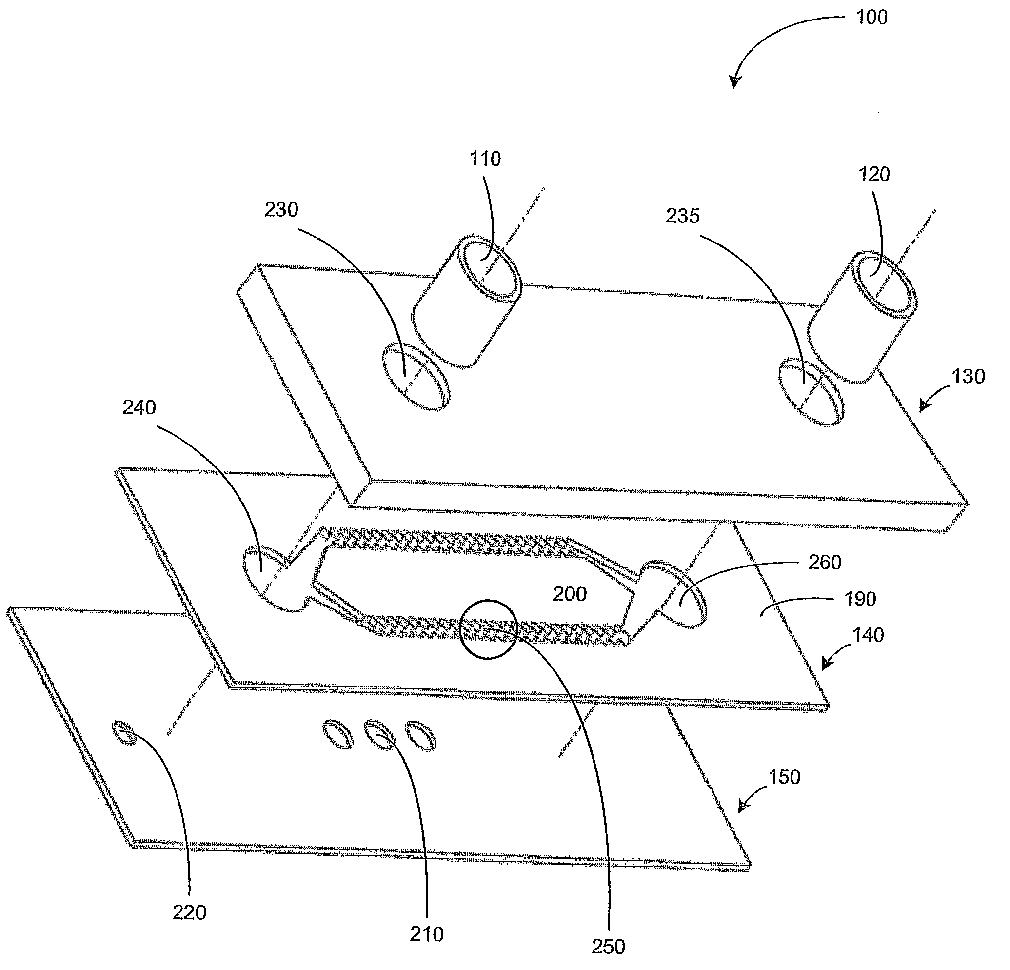
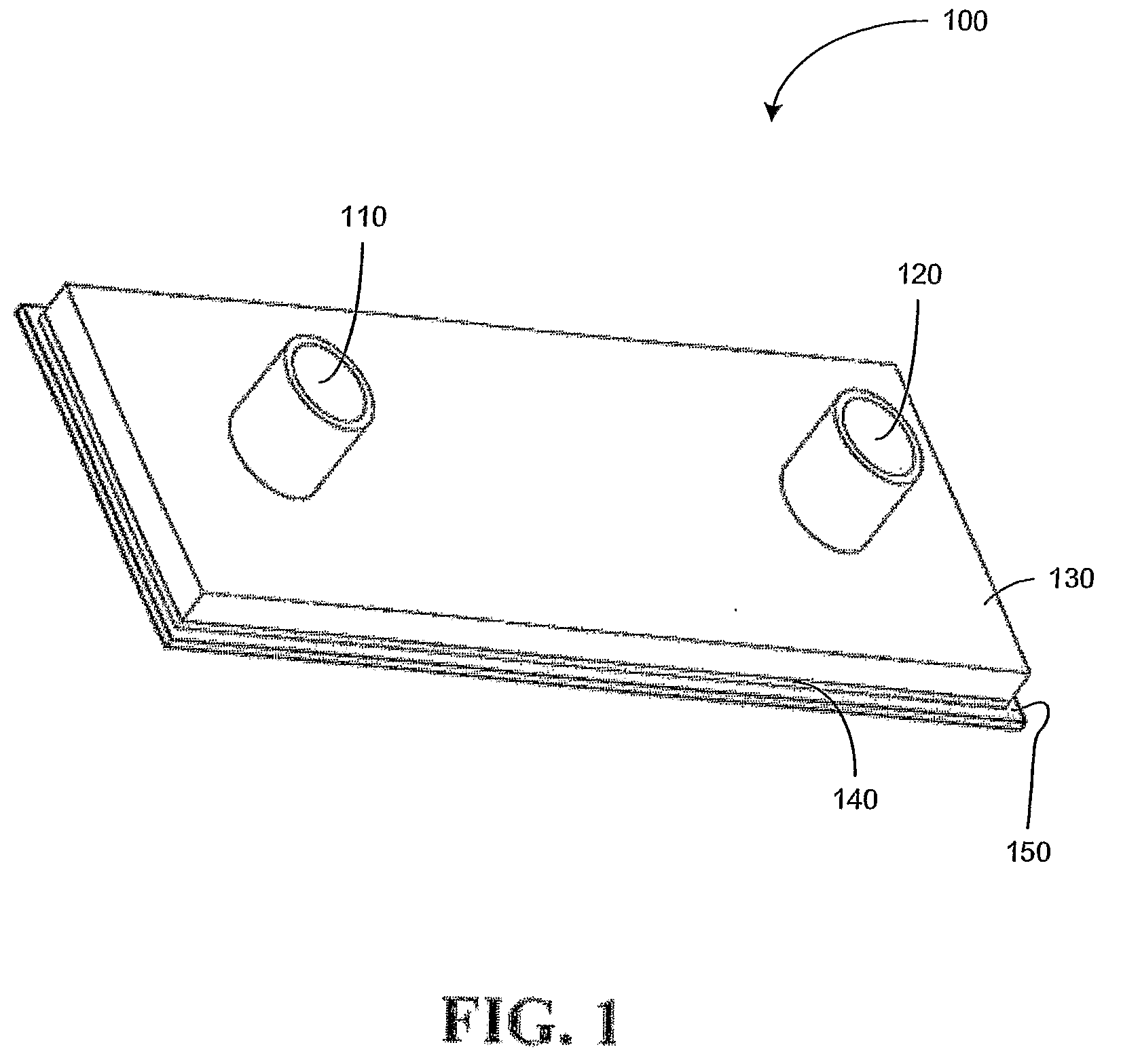
[0031]FIGS. 1 to 4 illustrate a device in the form of a biochip 100 exemplary of an embodiment of the present invention. As will become apparent, biochip 100 may be used for dielectrophoretic separation of biological material and lysing.

[0032]As illustrated in FIG. 1, biochip 100 includes an inlet 110, an outlet 120, top, middle and bottom layers 130, 140 and 150. Top layer 130 and bottom layer 150 are each formed as insulating wafers, formed for example composed of a material such as glass. Middle layer 140 is formed of a conductive material, such as for example silicon or metal.

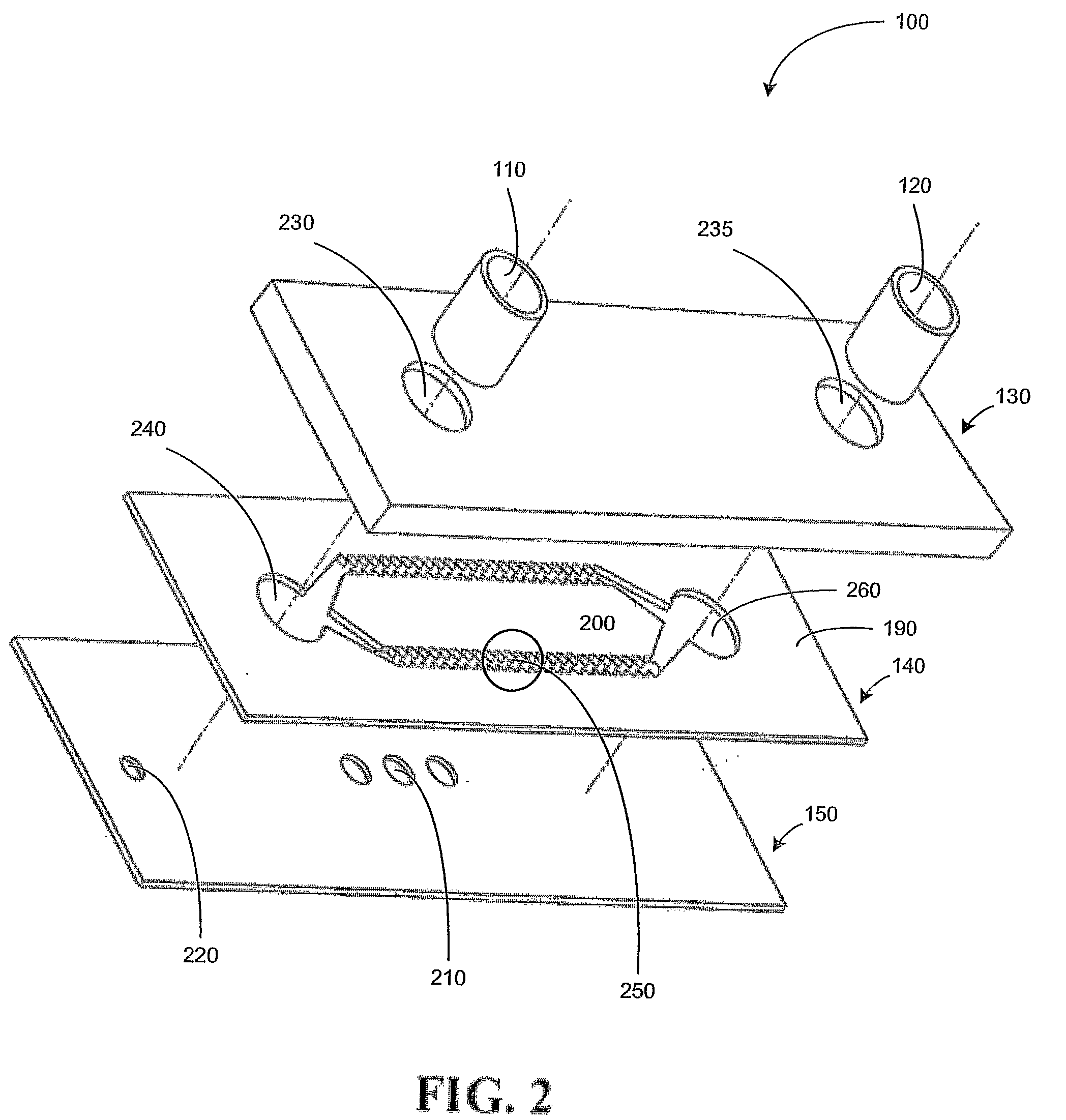
[0033]As illustrated in FIG. 2, a central portion of layer 140 forms a central electrode 200 and may be formed using etching or electroforming. The remainder of layer 140 acts as a bulk electrode 190. All three layers 130, 140, 150 are assembled to create a completely enclosed flow chamber defined by microfluidic channels 250. Top layer 130 and bottom layer 150 form a ceiling and floor of the flow chamber.

[...


PUM

PropertyMeasurementUnit
radiusaaaaaaaaaa
radiusaaaaaaaaaa
thicknessaaaaaaaaaa

Abstract

A biochip (100) for lysing and/or cell separation is formed to provide a sealed chamber for biological fluid. A conductive layer (140) bonded between upper (130) and lower (150) insulating layers is etched to form a microfluidic channel (250) between two electrodes (190, 200). The microfluidic channel connects a fluid inlet (11) and fluid outlet (120). The electrodes (190, 200) form an un-even electric field in the channel (250) to generate a dielectrophoretic force on the cells/particles within the sample fluid. A voltage source applies a suitable voltage to separate and/or lyse cells within the fluid.

Description

CROSS-REFERENCE TO RELATED APPLICATIONS[0001]This application claims benefits from U.S. Provisional Patent Application No. 60 / 586,718 filed Jul. 6, 2004, the contents of which are hereby incorporated herein by reference.FIELD OF THE INVENTION[0002]The present invention relates generally to a biological device for manipulating biological samples and more particularly to a lab-on-a-chip for sorting and lysing biological samples by dielectrophoresis and electroporation.BACKGROUND OF THE INVENTION[0003]A growing area of research in the fields of bioengineering and nanotechnology relates to the creation of integrated miniature devices capable of performing chemical and biochemical analysis of biological matter. Such devices are known as micro-total analysis systems (μ-TAS) or a lab-on-a-chip. These devices are becoming increasingly popular in biomedical research, disease diagnosis, food pathogen detection, environmental analysis and forensics. The devices are portable, require reduced sa...

Claims


Application Information

Patent Timeline
Patent Type & Authority Applications(United States)
IPC IPC(8): C12N13/00C12M1/00
CPCB01L3/502707B01L3/502761B01L2200/0647B01L2300/0816B01L2300/0864C12M47/06B03C5/005B03C5/026B03C2201/26C12M47/04B01L2400/0424
Inventor ILIESCU, CIPRIANXU, GUOLINTAY, FRANCIS ENG-HOCK
Owner AGENCY FOR SCI TECH & RES
Why Eureka
Try Eureka