Exhaust gas purification device of internal combustion engine

a technology of exhaust gas purification device and internal combustion engine, which is applied in the direction of machines/engines, mechanical equipment, transportation and packaging, etc., can solve the problems of blocked fuel injection path, difficult to reach the inside of the fuel injection path, and difficult to flow exhaust gas through the exhaust passage. , to achieve the effect of simple structure, simple structure and simple structur

Active Publication Date: 2009-06-25
MITSUBISHI MOTORS CORP
View PDF4 Cites 39 Cited by
  • Summary
  • Abstract
  • Description
  • Claims
  • Application Information

AI Technical Summary

Benefits of technology

[0016]The scavenging flow forming means is, in a preferred aspect of the present invention, provided with a collision portion where the exhaust gas introduced from the inflow path collides against the wall surface of the injection path and is configured so that the inside of the injection path is scavenged by the flow of the exhaust gas generated by the collision. Thereby, the scavenging in the injection path can be effectively carried out with a simple structure.
[0017]Also, the scavenging flow forming means has, in another preferred aspect of the present invention, the inflow path opened in the injection path with offset to an axis of the injection path so that a swirl flow of the exhaust gas is generated in the injection path, and the inside of the injection path is scavenged by the swirl flow. Thereby, the inside of the injection path can be effectively scavenged also by a simple structure.
[0018]In another preferred aspect of the present invention, the exhaust passage has a bent portion, and the injection path extends outward in the middle of the bent portion in the exhaust passage. Thereby, a structure for scavenging easily in the injection path utilizing a fork portion formed by the injection path of the additive and the bent portion can be constructed.
[0019]Also, in another preferred aspect of the present invention, the injection path is formed by a pipe member provided separately from the exhaust passage and having its distal end portion projecting into the exhaust passage, and the inflow portion is formed at the distal end of the pipe member and is a notched portion for receiving a part of the exhaust gas flowing in the exhaust passage. Thereby, with a simple structure using a pipe member in which a notched portion is formed at the distal end portion, the scavenging in the injection path of the additive can be carried out.
[0020]The notched portion is formed by diagonally notching the distal end portion of the pipe member in the preferred aspect so as to have an introduction portion for receiving a part of the exhaust gas flowing in the exhaust passage. Thereby, with a simple structure, the scavenging in the injection path of the additive can be carried out.

Problems solved by technology

Since in such a structure that the fuel is injected from a point far from the exhaust gas flow, the fuel injection path is retreated from the exhaust passage, a flow of the exhaust gas flowing through the exhaust passage is hard to reach the inside of the fuel injection path.
Since the deposit is accumulated on the wall surface of the fuel injection path every time the fuel is injected, there is a possibility that the fuel injection path is blocked by the accumulated deposit.

Method used


Image

  • Exhaust gas purification device of internal combustion engine
  • Exhaust gas purification device of internal combustion engine
  • Exhaust gas purification device of internal combustion engine

Examples


first embodiment

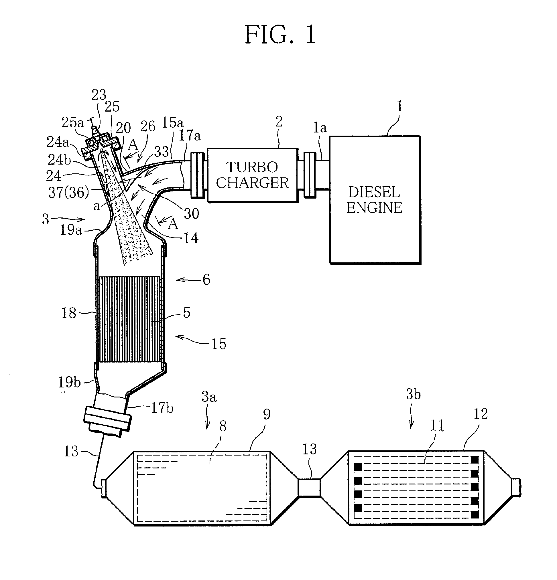
[0047]The present invention will be described below on the basis of a first embodiment illustrated in FIGS. 1 to 5.

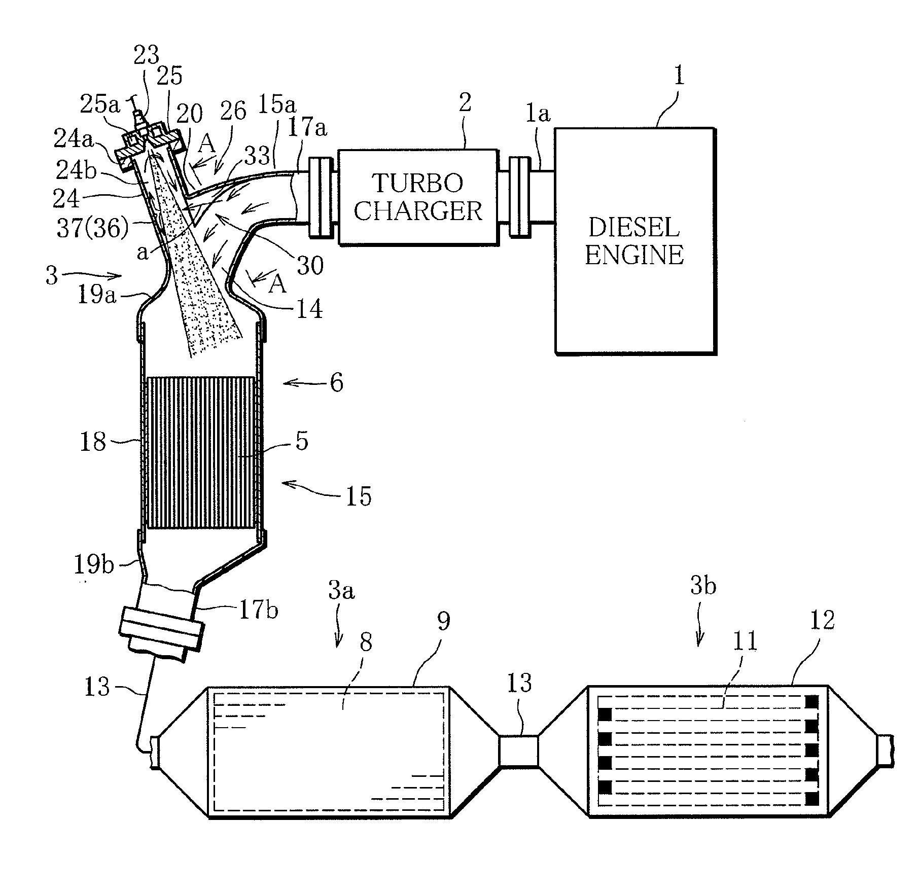
[0048]FIG. 1 shows an exhaust system of internal combustion engine such as a diesel engine, for example. Reference numeral 1 in the figure denotes an engine main body in a diesel engine, 1a to an exhaust manifold (only a part of it is shown) of the engine main body 1, and 2 to a turbo charger connected to an outlet of the exhaust manifold 1a, respectively.

[0049]At an exhaust outlet of the turbo charger 2, an exhaust gas purification device 3 is provided. In the exhaust gas purification device 3, a structure in which a NOx removing system 3a for storing NOx (nitrogen oxides) in the exhaust gas and regularly reducing and removing the stored NOx and a PM trap system 3b for trapping PM (particulate matter) are combined is used.

[0050]For example, in the NOx removing system 3a, configuration in which a catalyst converter 6 connected from the exhaust outlet of the turbo charge...

second embodiment

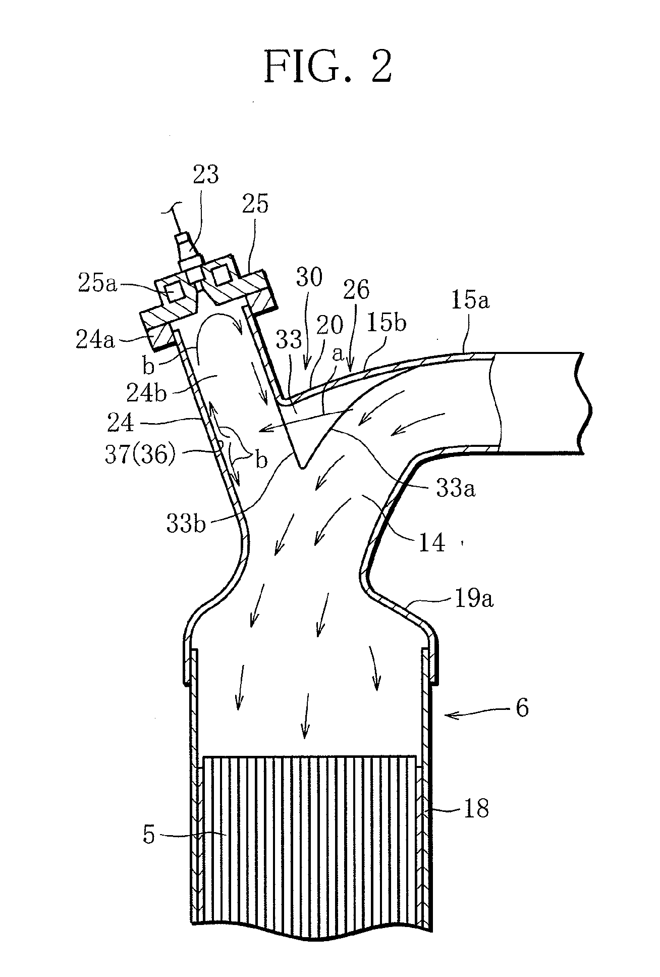
[0067]FIGS. 6 to 9 illustrate the present invention.

[0068]In this embodiment, the fuel injection path 24b is scavenged using another swirl-type inflow portion 40 separate from the collision-type scavenging portion in the first embodiment.

[0069]Specifically, an inflow portion 40 of the present embodiment has the outlet 33b of the inflow portion 33 opened at a point offset to the side from the center of the fuel injection path 24b, more specifically, a point in a tangent direction of the fuel injection path 24b as the scavenging-flow forming means 36 as shown in FIGS. 8 and 9 so that the exhaust gas is introduced into the fuel injection path 24b along the circumference from the downstream side of the fuel injection path 24.

[0070]By the introduction of the exhaust gas, a swirl flow α is generated in the fuel injection path 24b as shown in FIGS. 6 to 8, and the evaporated fuel and soot accumulated in the fuel injection path 24b is sucked out by a negative pressure generated at the cente...

third embodiment

[0073]FIGS. 10 and 11 illustrate the present invention.

[0074]The present embodiment employs an inflow path 43 in a separate structure, not the inflow path 33 in an integral structure as in the first embodiment.

[0075]Specifically, the inflow path 43 has one end portion of an exhaust gas introduction pipe member 45 constituted by a pipe member communicating with a point on the downstream side of the fuel injection path 24b and the other end portion communicating with a portion 15b in the exhaust passage 15 immediately upstream from the fuel injection path 24b and is formed by connecting the both to each other by an exhaust gas introduction pipe portion 45. The scavenging structure can be also constructed easily with this structure.

[0076]The exhaust gas flowing from the inflow path 43 into the fuel injection path 24b collides against the collision portion 37 on the wall surface of the fuel injection path 24b similarly to the scavenging-flow forming means 36 in the first embodiment so a...


PUM

PropertyMeasurementUnit
heat-resistant temperatureaaaaaaaaaa
temperatureaaaaaaaaaa
shapeaaaaaaaaaa

Abstract

The exhaust gas purification device of an internal combustion engine of the present invention comprises an exhaust passage for guiding an exhaust gas exhausted from an engine to outside, a catalyst provided in the exhaust passage, an injection path connected on an upstream side of the catalyst in the exhaust passage, an additive injection valve installed in the injection path for supplying an additive to the catalyst through the injection path, and an inflow portion provided in a merging portion where the exhaust passage and the injection path merge for having a part of the exhaust gas flowing in the exhaust passage flow into the injection path.

Description

BACKGROUND OF THE INVENTION[0001]1. Field of the Invention[0002]The present invention relates to an exhaust gas purification device of an internal combustion engine having a structure for injecting an additive to be supplied to a catalyst.[0003]2. Description of the Prior Art[0004]For purification of an exhaust gas of a diesel engine vehicle (vehicle), in order to prevent emission of NOx (nitrogen oxides) and PM (particulate matter) contained in exhaust gas of a diesel engine into the air, an exhaust gas purification device in which NOx trap catalyst, selective reduction NOx catalyst, diesel particulate filter and the like are combined is used.[0005]In this type of an exhaust gas purification device, such a structure is employed that in an exhaust passage for exhausting an exhaust gas exhausted from an engine to the outside, an oxidation catalyst, a NOx trap catalyst, a selective reduction NOx catalyst and the like called pre-stage catalyst is provided, and on an upstream side of th...

Claims


Application Information

Patent Timeline
Patent Type & Authority Applications(United States)
IPC IPC(8): F01N3/20F01N13/10
CPCF01N3/2066F01N3/2892F01N13/08F01N2570/04F01N2570/10F01N13/009F01N2610/03F01N2610/1453F02B37/00Y02T10/24F01N2570/14Y02T10/12B01F23/2132B01F2025/931B01F25/314F01N3/28F01N3/20
Inventor KIMURA, HIROYUKIKOJIMA, MITSUTAKAOKADA, KOJIROSHIGAHARA, KEIHATA, MICHIHIROKAWASHIMA, KAZUHITOKOGA, KAZUOMAEHARA, KAZUTOISHII, HAJIME
Owner MITSUBISHI MOTORS CORP
Why Eureka
Try Eureka