Gas imaging system

a gas imaging and gas technology, applied in the field of gas imaging systems, can solve the problems of releasing toxic or explosive gas into the surrounding environment, creating many safety and environmental problems, and reducing the safety of users, and achieve the effects of being convenient to carry, easy to operate, and convenient to carry

Inactive Publication Date: 2009-06-25
DAYLIGHT SOLUTIONS
View PDF52 Cites 42 Cited by
  • Summary
  • Abstract
  • Description
  • Claims
  • Application Information

AI Technical Summary

Benefits of technology

[0006]Embodiments of the present invention are directed to imaging systems for capturing an image of an emitting gas. In one embodiment, the imaging system includes an imager and a laser source. The imager captures an image of light in the mid-infrared (MIR) range. The laser source includes a semiconductor laser that directly emits (without frequency conversion) an output beam that is in the MIR range. In this embodiment, the output beam is directed at the emitting gas and is adapted to backscatter near and/or be absorbed by the emitting gas. For example, the output beam ca

Problems solved by technology

The usage, transportation, and storage of hazardous materials create many safety and environmental issues.
More specifically, during usage, transportation, and storage of hazardous materials, leaks can release toxic or explosive gas into the surrounding environment.
For example, industrial equipment used in the oil, gas, utility, and chemical industries can release toxic gas into the surrounding environment.
As another example, hazardous gases can pose a threat to homeland security.
In many cases, the hazardous gas is odorless, colorless, and spreads quickly.
As a result thereof, it can be quite difficult to detect and loc

Method used


Image

  • Gas imaging system
  • Gas imaging system
  • Gas imaging system

Examples


Embodiment Construction

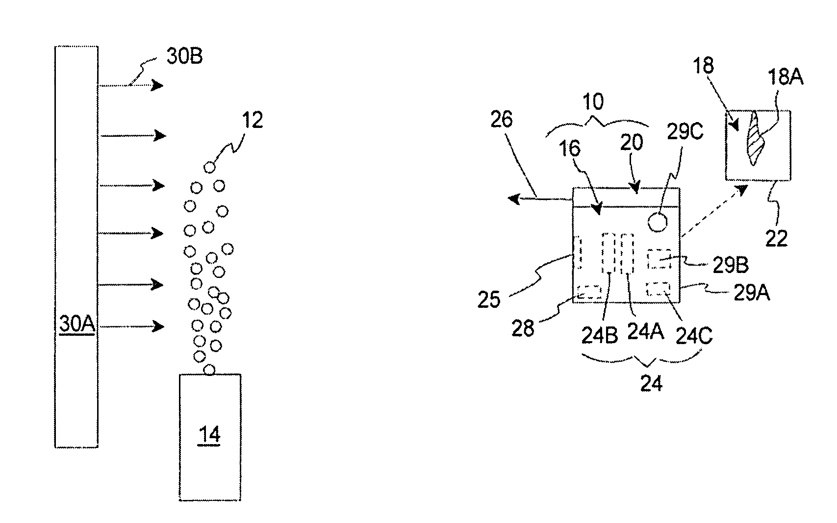
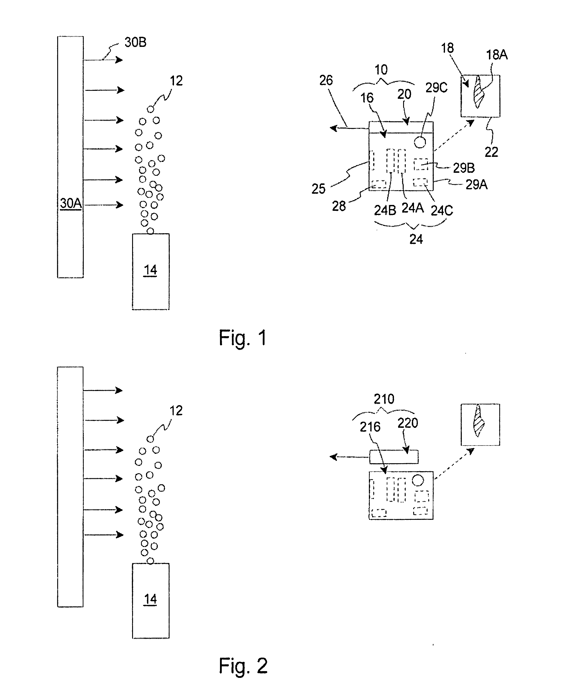
[0030]FIG. 1 illustrates a simplified side illustration of a gas imaging system 10 that is suited for imaging, locating, detecting, and / or identifying an emitting gas 12 that is emitting from a gas source 14. In one embodiment, the gas imaging system 10 includes a mid-infrared (MIR) imager 16 that provides an image 18 of the emitting gas 12, and an MIR laser source 20 that illuminates the area near the emitting gas 12 and significantly improves the image 18 captured by the MIR imager 16. As a result thereof, the gas imaging system 10 can be used to quickly and accurately locate and / or identify the emitting gas 12 even if there is little or no temperature difference between the emitting gas 12 and the surrounding environment.

[0031]Further, in certain embodiments, because of the unique design disclosed herein, the gas imaging system 10 can be extremely compact, hand-held, lightweight, stable, rugged, small, self-contained, and portable. For example, the imaging system 10 can have dime...


PUM


Abstract

An imaging system (10) for imaging an emitting gas (12) includes an imager (16) and a laser source (20). The imager (16) captures an image (18) of light in the mid-infrared (MIR) range. The laser source (20) includes a semiconductor laser (334) that directly emits an output beam (26) that is in the MIR range. The output beam (26) may be adapted to backscatter near and/or be absorbed by the emitting gas (12). Thus, when an emitting gas (12) is present, the gas (12) may absorb and attenuate the backscattered light. As a result thereof, a shadow or contrast (18A) corresponding to the emitting gas (12) may be visible in the image (18) that is captured by the imager (16).

Description

BACKGROUND OF THE INVENTION[0001]The present invention relates generally to imaging systems and, more particularly to imaging of gas emissions.[0002]The usage, transportation, and storage of hazardous materials create many safety and environmental issues. More specifically, during usage, transportation, and storage of hazardous materials, leaks can release toxic or explosive gas into the surrounding environment. For example, industrial equipment used in the oil, gas, utility, and chemical industries can release toxic gas into the surrounding environment. As another example, hazardous gases can pose a threat to homeland security. In many cases, the hazardous gas is odorless, colorless, and spreads quickly. As a result thereof, it can be quite difficult to detect and locate the source of the leak.[0003]In one specific example, sulfur hexafluoride (“SF6”) is commonly used as an insulator for high voltage electrical equipment. SF6 is an inert gas that is relatively expensive and is a gr...

Claims


Application Information

Patent Timeline
IPC IPC(8): G01N21/35
CPCG01M3/202G01M3/38G01N21/3504G01N2021/3513H01S5/141H01S5/0222H01S5/024H01S5/02415H01S5/0612H01S3/105
Inventor WEIDA, MILES JAMESDAY, TIMOTHYTAKEUCHI, ERIC B.
Owner DAYLIGHT SOLUTIONS
Why Eureka
Try Eureka