Display element and display device

a display element and display device technology, applied in the field of display elements and display devices, can solve the problems of inability to enlarge the temperature range of driving in principle, weak phase, and inability to resist the application of electric fields and reliability, and achieve wide viewing angles, high contrast properties, and high speed response.

Inactive Publication Date: 2009-06-25
SHARP KK
View PDF39 Cites 33 Cited by
  • Summary
  • Abstract
  • Description
  • Claims
  • Application Information

AI Technical Summary

Benefits of technology

[0037]Accordingly, with the aforementioned arrangement, it is possible to realize a display device that has high-speed response property, wide viewing angle property, and high contrast property, that has a wide temperature range for driving, and that is excellent in durability and reliability. The display element of the present invention has high-speed response property as described above. Accordingly, by use of this property, the display element is applicable to a display device of a field sequential color mode of performing time sharing driving in which colors of a light source such as a backlight are switched at high speed in one unit field so as to perform display.

Problems solved by technology

However, as the display element disclosed in Patent Document 1 uses a pure isotropic phase of a liquid crystal material, it is impossible in principle to enlarge the temperature range for driving.
Further, as the technique disclosed in Patent Document 2 uses a blue phase that has not been put into practical use in a display device, the technique is unknown in terms of specific factors such as quality and reliability, and accordingly the technique is still suspicious in terms of durability against application of an electric field and reliability.
That is, as the blue phase is an unstable phase in essence, even when the blue phase is stabilized using a polymer network, the blue phase is weaker than, for example, a nematic phase used in a conventional liquid crystal display device in terms of repeated switching on / off of an electric field and application of a high electric field.
That is, the techniques disclosed in Patent Documents 3 and 4 cannot attain high-speed response property, wide viewing angle property, and high contrast property that are essential properties of the display device utilizing the Kerr effect.

Method used


Image

  • Display element and display device
  • Display element and display device
  • Display element and display device

Examples


embodiment 1

(Structure of Display Element 20)

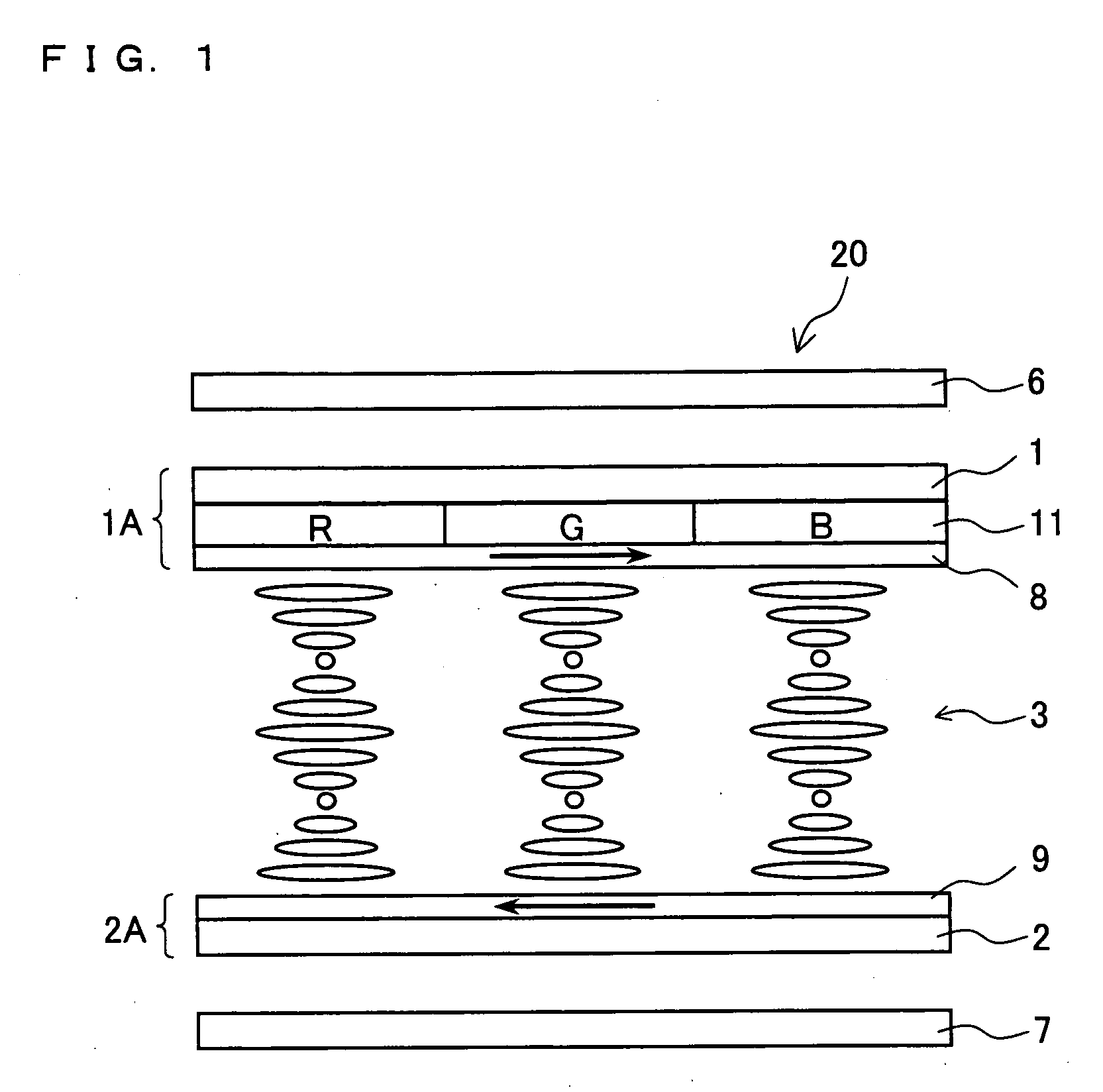
[0114]The following explains an embodiment of the present invention with reference to drawings. FIG. 1 is a cross-sectional drawing schematically illustrating an outline structure of a display element 20 of the present embodiment. FIG. 4 is a block diagram schematically illustrating an outline structure of a main part of a display device 100 including the display element 20. FIG. 5 is an equivalent circuit diagram schematically illustrating an outline structure of a periphery of the display element 20.

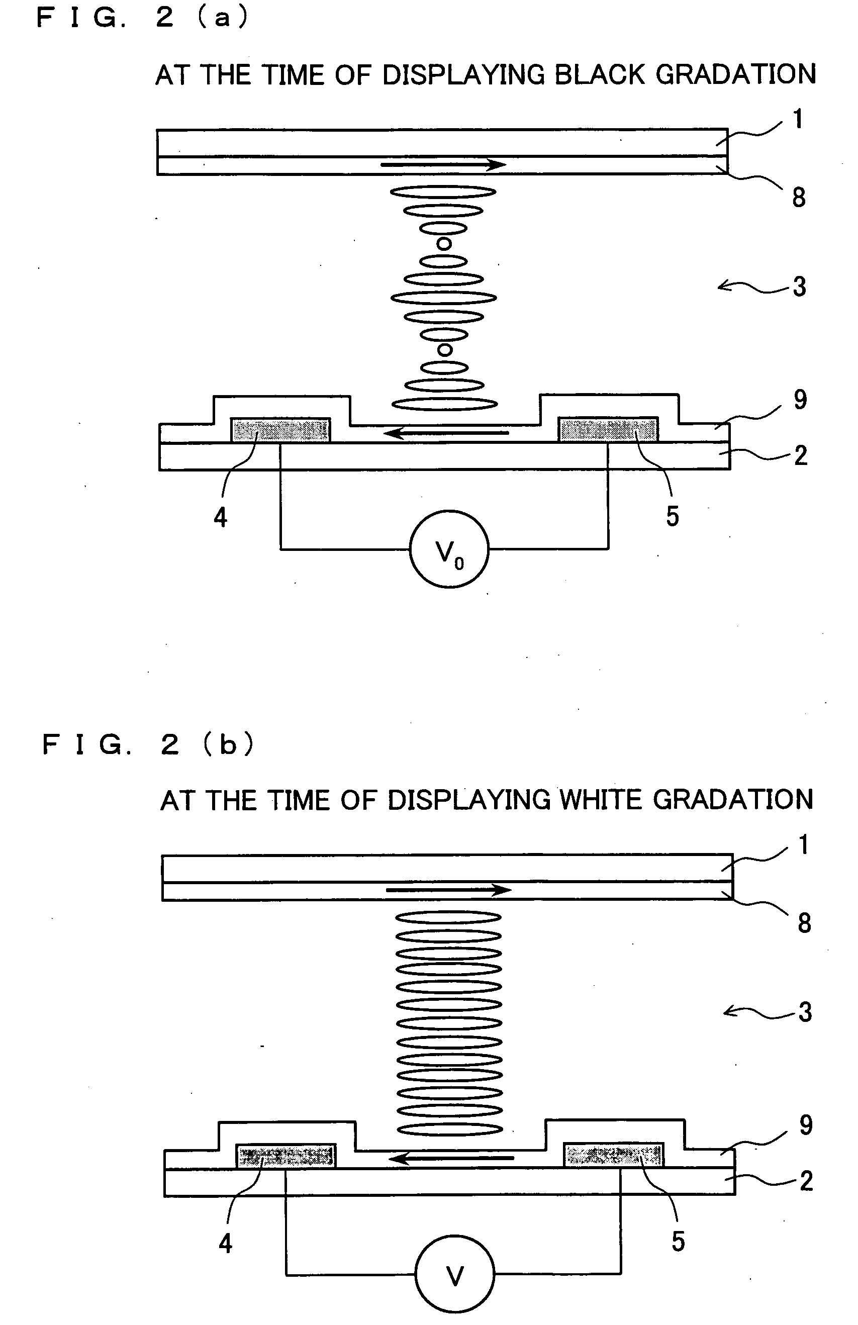
[0115]The display element 20 of the present embodiment uses as an optical modulation layer a cholesteric liquid crystal layer that exhibits optical isotropy in a direction parallel to a plane of a substrate at a time when no electric field is applied, and the display element 20 performs display by applying an electric field on the cholesteric liquid crystal layer so as to exhibit optical anisotropy in the direction parallel to the plane of the substrate...

embodiment 2

[0210]The following explains another embodiment of the present invention. For convenience of explanation, members having the same functions as those explained in Embodiment 1 are given the same reference numerals and explanations thereof will be omitted here.

[0211]As shown in Table 1 in Embodiment 1, a liquid crystal cell to which liquid crystals have been poured and which has been subjected to a re-aligning treatment exhibits complete optical isotropy (transparent state) in a direction perpendicular to a plane of a substrate. On the other hand, the V-T property of FIG. 7 and the response property of FIG. 9(a) show that the complete optical isotropy (transparent state) equal to an original alignment state is not realized after application of a voltage is stopped, and some amount of light leaks. That is, in measuring electro-optical property, liquid crystals do not instantly go back to its initial optical isotropy state after application of a voltage is stopped.

[0212]This is because,...

embodiment 3

[0247]The following explains further another embodiment of the present invention. For convenience of explanation, members having the same functions as those explained in Embodiment 1 or 2 are given the same reference numerals and explanations thereof will be omitted here.

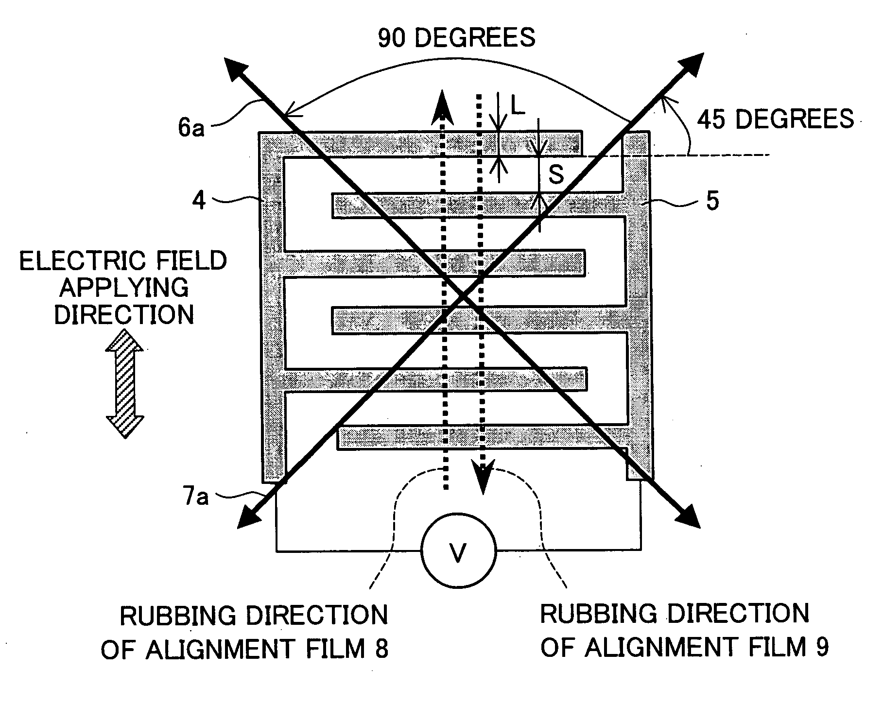
[0248]FIG. 12 is a plan drawing showing pectinate electrodes 4a and 5a included in a display element 20a of the present embodiment, the pectinate electrodes 4a and 5a being seen from a direction normal to a plane of a substrate. As shown in FIG. 12, each pixel of the display element 20a is provided with an electrode couple 10 including the pectinate electrodes 4a and 5a. The electrode couple 10 includes at least two domains having different directions in which electric fields are applied. That is, as shown in FIG. 12, the electrode couple 10 includes a domain where pectinate parts 4aa and 5aa are provided and a domain where pectinate parts 4ab and 5ab are provided. A direction in which the pectinate parts 4aa and 5a...


PUM

PropertyMeasurementUnit
bending angleaaaaaaaaaa
angleaaaaaaaaaa
temperatureaaaaaaaaaa

Abstract

A display element having high response property, wide viewing angle property, and high contrast property, and exhibiting a wide driving temperature range and excellent durability and reliability. Between two facing substrates (1, 2), a cholesteric liquid crystal layer (3) made of a liquid crystal material exhibiting a cholesteric phase whose spontaneous twist pitch is shorter than a wavelength of visible light is provided. Facing planes of the substrates (1, 2) are provided with alignment films (8, 9) for aligning liquid crystal molecules near the interface of the substrate in a specific direction. Furthermore, the planes are provided with electrodes (4, 5) for applying an electric field on the cholesteric liquid crystal layer (3) in a direction substantially parallel to a plane of each substrate. The cholesteric liquid crystal layer (3) exhibits optical isotropy in the direction parallel to the plane of each substrate when no voltage is applied. Display is performed by applying an electric field on the cholesteric liquid crystal layer (3) so as to exhibit optical anisotropy in the direction parallel to the plane of each substrate.

Description

TECHNICAL FIELD[0001]The present invention relates to a display element and a display device, having high-speed response property, wide viewing angle property, and high contrast property, and exhibiting a wide temperature range for driving and are excellent in durability and reliability.BACKGROUND ART[0002]Liquid crystal display elements are advantageous in terms of their thin thickness, lightweight, and consumption of less power compared with other display elements. For that reason, liquid crystal display elements are widely used for image display devices such as TVs and monitors, OA (Office Automation) apparatuses such as word processors and personal computers, and image display devices mounted to video cameras, digital cameras, and information terminals such as mobile phones.[0003]Conventional examples of liquid crystal display methods of liquid crystal display elements include: a twisted nematic (TN) mode using nematic liquid crystals; a display mode using ferroelectric liquid c...

Claims


Application Information

Patent Timeline
Patent Type & Authority Applications(United States)
IPC IPC(8): G02F1/13G02F1/1335
CPCG02F1/133707G02F1/134363G09G2320/0252G09G3/3648G09G2310/06G02F1/13718
Inventor INOUE, IICHIROMIYACHI, KOICHISHIBAHARA, SEIJI
Owner SHARP KK
Why Eureka
Try Eureka