Dynamic range controller

a range controller and dynamic range technology, applied in the direction of gain control, volume compression/expansion, digital transmission, etc., can solve the problems of large signal amplitude, high power consumption, and delay of 6 ms, so as to prevent audible clipping of audio signals, reduce gain, and bring output amplitude within the clipping level sufficiently quickly

Active Publication Date: 2009-06-25
CIRRUS LOGIC INC
View PDF4 Cites 48 Cited by
  • Summary
  • Abstract
  • Description
  • Claims
  • Application Information

AI Technical Summary

Benefits of technology

[0024]Such an input signal may be in the log domain, the attack rate linearly reducing the level of the input signal over the time T to within the maximum permitted level.
[0038]By means of the present invention, an attack rate used in a dynamic range controller to reduce a gain applied to a signal can be adaptively controlled, based on an amplitude in excess of a clipping level which would otherwise be expected, and the delay time available. Therefore, it can be ensured that the output amplitude is brought within the clipping level sufficiently quickly to prevent audible clipping of an audio signal, and / or to avoid excessive power consumption of downstream circuitry.

Problems solved by technology

A problem can occur if a low level signal is applied, followed by a high level signal.
For an audio signal, this clipping will cause audible distortion.
Moreover, such a large signal amplitude will consume a considerable amount of power, which in itself can be problematic in battery-powered apparatus such as a portable audio player or mobile telephone.
Unfortunately, to prevent clipping completely, in this example a delay of 6 ms is required.
Additionally, such a long delay is undesirable in many applications such as real-time processing.

Method used


Image

  • Dynamic range controller
  • Dynamic range controller
  • Dynamic range controller

Examples


Embodiment Construction

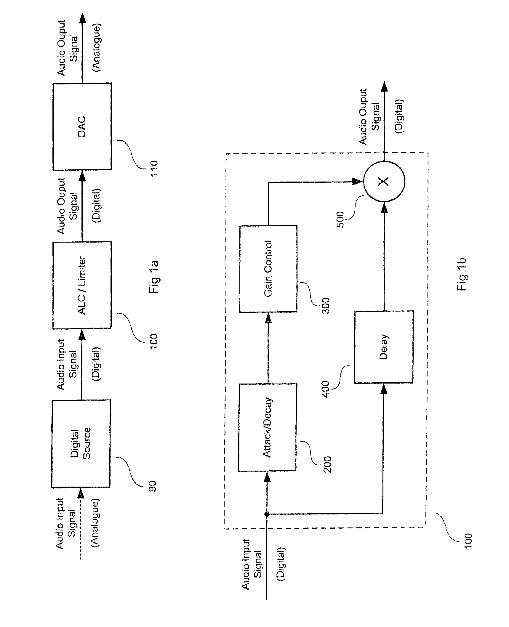
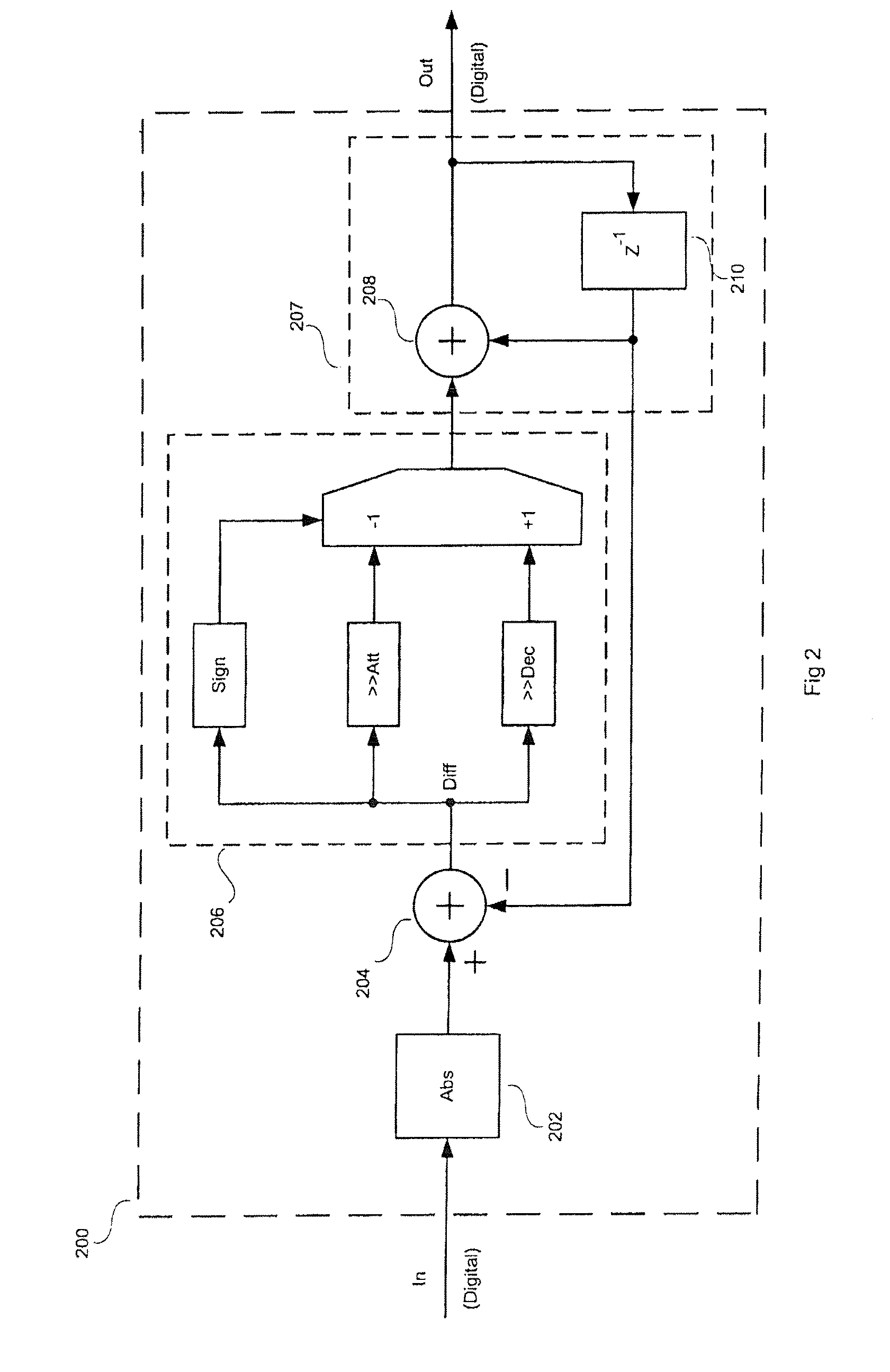
[0050]An embodiment of the present invention will now be described with reference to the drawings. Before describing the constituent parts of the embodiment in detail, the underlying principle will first be explained by referring to FIG. 5.

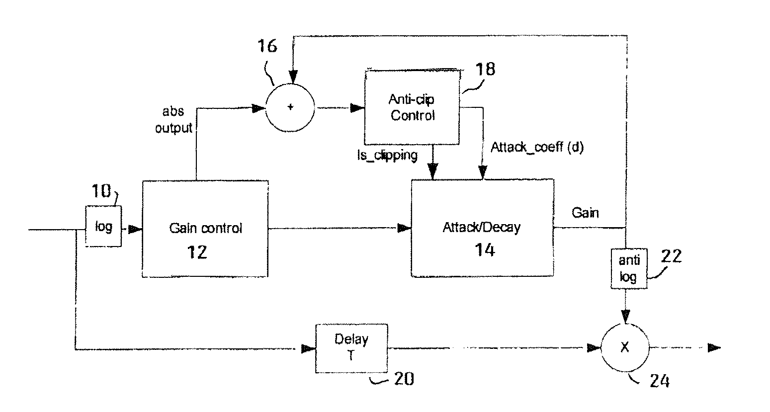
[0051]The invention prevents or reduces clipping in a system comprising a dynamic range controller without the need for a large delay, by adaptively adjusting the attack rate according to the signal size and delay T in the system. The dynamic range controller (ALC / Limiter) first finds an estimate of the output level which is predicted to occur with the current gain applied. In the example shown by the upper graph in FIG. 5, the gain is high enough to cause clipping when the signal level rises above the lower dashed line marked “Clip level”. The signal level reaches a maximum of ‘d’ dB above the clip level. To prevent clipping, the gain must be attenuated by d dB in time T (see the lower graph in FIG. 5). If the delay is N samples, the Anti-clip co...


PUM


Abstract

A circuit for preventing clipping in an Automatic Level Control (ALC) or Limiter, where the amplitude of the signal above the clipping point is estimated, then the signal level is automatically reduced over a defined period substantially equal to the feedforward delay in the ALC / Limiter. By adaptively controlling, based on the excess amplitude and the delay time available, an attack rate used in the ALC / Limiter to reduce the gain applied to an input signal, it can be ensured that the output amplitude is brought within the clipping level sufficiently quickly to prevent audible clipping.

Description

FIELD OF THE INVENTION[0001]The present invention relates to a dynamic range controller such as an Automatic Level Controller (ALC) and / or Limiter. More particularly, but not necessarily exclusively, the present invention concerns an anti-clip circuit or function added to a dynamic range controller, such as one used for processing digital audio signals.BACKGROUND OF THE INVENTION[0002]Automatic Level Controllers (ALCs) and Limiters are used for controlling the dynamic range of a signal, usually, but not always, an audio signal. Typically, low level audio signals are boosted to improve audibility, and high-level signals are attenuated to prevent clipping i.e. distortion. ALCs / Limiters are often used in portable equipment with microphones so that sound sources which are a long way from the microphone are boosted to the same level as sound sources close to the microphone. In the rest of this specification, the term “dynamic range control” will be used to cover both ALC and Limiter func...

Claims


Application Information

Patent Timeline
IPC IPC(8): H03G3/30
CPCH03G7/007
Inventor MAGRATH, ANTHONY JAMES
Owner CIRRUS LOGIC INC
Why Eureka
Try Eureka