System and Method for Ultrasonic Assisted EDM Machining

a technology of edm machining and ultrasonic energy, applied in the direction of electrode support devices, manufacturing tools, electromechanical vibration holders, etc., can solve the problems of reducing the machining time of edm, processing can be quite slow, and the blade is not easy to efficiently couple ultrasonic energy to the blad

Active Publication Date: 2009-07-02
SONICS & MATERIALS
View PDF10 Cites 10 Cited by
  • Summary
  • Abstract
  • Description
  • Claims
  • Application Information

AI Technical Summary

Benefits of technology

[0008]In some embodiments, the female part has generally the same shape as and smaller dimensions tha

Problems solved by technology

While such process provides several advantages over other known alternatives, as is known, the process can be quite slow.
Therefore, applying ultrasonic energy to the turbine blade reduces the EDM machining time.
However, the problem exists as to how to efficiently couple ultrasonic energy to the blade.
However, this is a very difficult task to accomplish because the combination of the horn, blade and clamp must sustain the ultrasonic vibrations.
Problem

Method used


Image

  • System and Method for Ultrasonic Assisted EDM Machining
  • System and Method for Ultrasonic Assisted EDM Machining
  • System and Method for Ultrasonic Assisted EDM Machining

Examples


Embodiment Construction

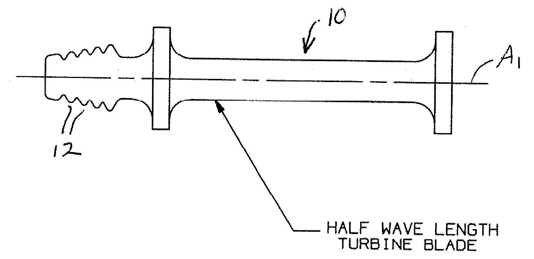
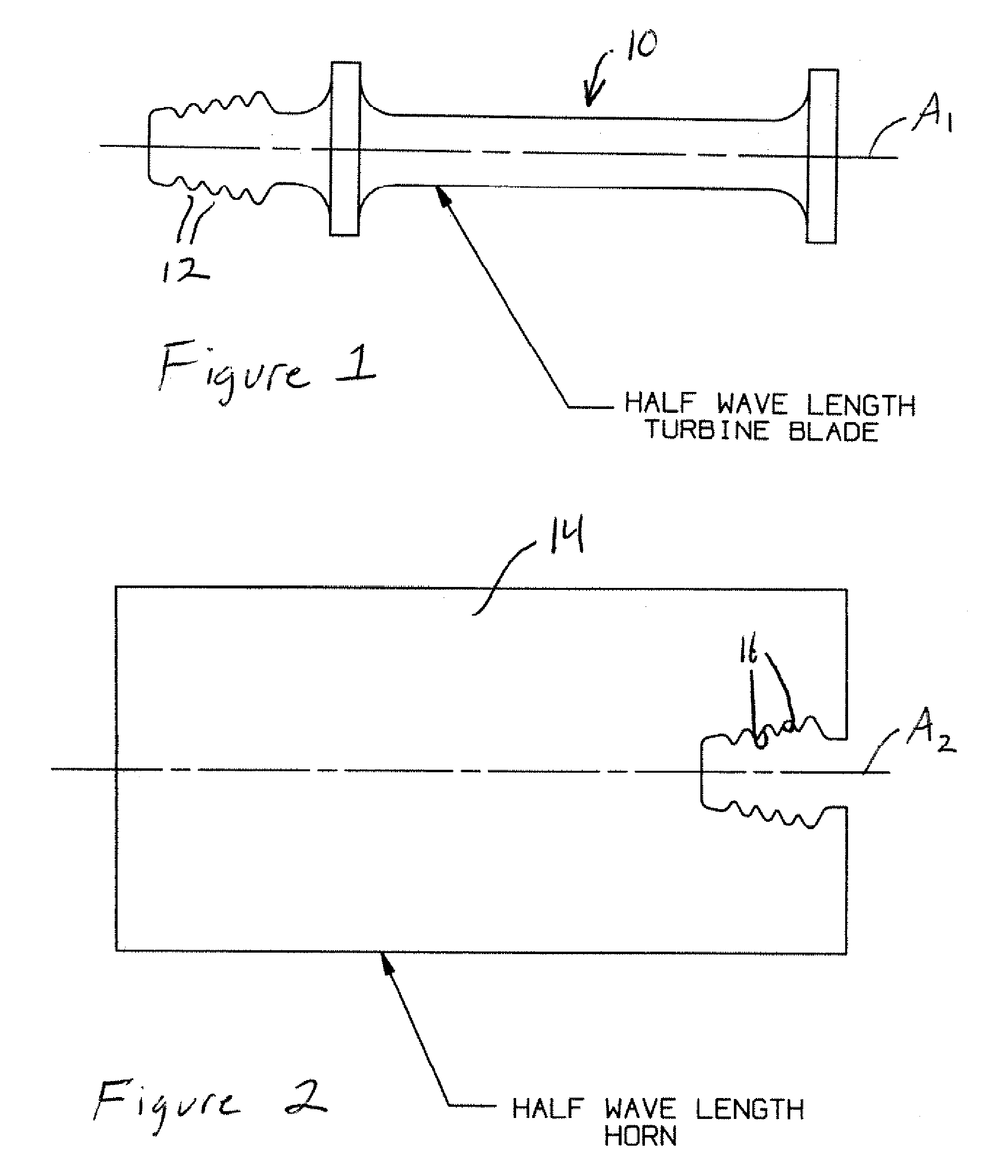
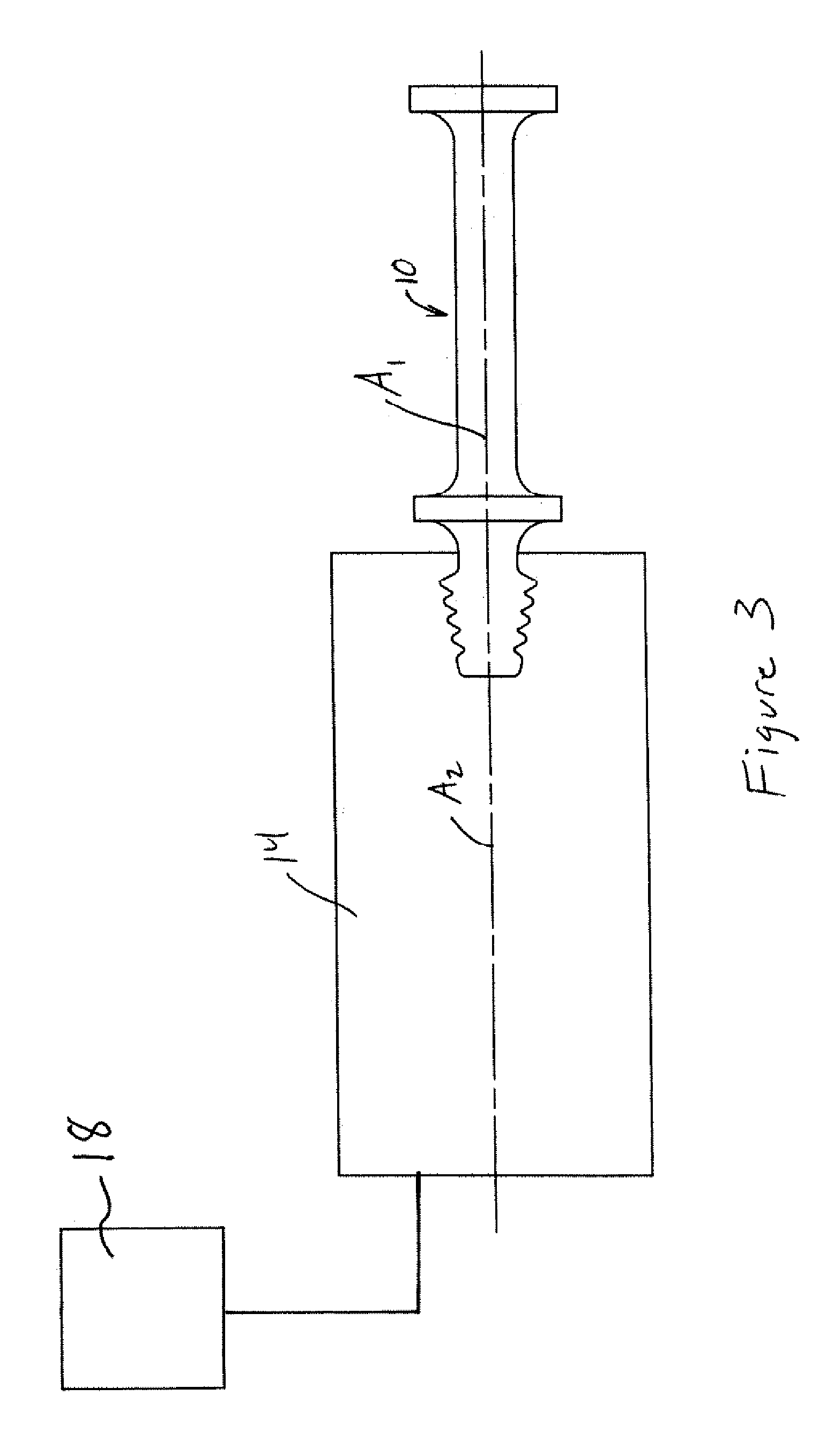
[0022]The present invention stems from the fact that every turbine blade 10 (shown schematically in FIG. 1) has tangs 12 at one end that are used to attach it to a rotating shaft (not shown) after manufacture of the blade 10. Applicant has discovered that attachment of the blade 10 to a horn can be accomplished by making a horn 14 (shown schematically in FIG. 2) having the same resonant frequency as the turbine blade 10 with slightly smaller mating female tangs 16, as compared to the male tangs 14 of the blade 12, which are then heated to capture the tangs 12 of the blade 10 by fitting the blade 10 at the output end of the horn 14.

[0023]The horn 14 may be made from either titanium or aluminum, for example, since both of these metals have a greater coefficient of expansion than the steel turbine blades 10. To accomplish the inventive attachment method, the horn 14 is heated up to expand the mating section thereof (i.e., the female tangs 16) so that the mating section of the blade 10 ...


PUM

PropertyMeasurementUnit
Temperatureaaaaaaaaaa
Frequencyaaaaaaaaaa
Energyaaaaaaaaaa

Abstract

A system for ultrasonic assisted electrical discharge machining of a component part having a longitudinal axis, a half wavelength resonant frequency along the longitudinal axis and an attachment portion, is provided. The system includes an ultrasonic horn having a longitudinal axis, a half wavelength resonant frequency along the longitudinal axis and an attachment portion. The half wavelength resonant frequency of the ultrasonic horn is the same as the half wavelength resonant frequency of the component part. Additionally, one of the attachment portion of the component part and the attachment portion of the ultrasonic horn is a male part and the other one of the attachment portion of the component part and the attachment portion of the ultrasonic horn is a female part sized and shaped to mate and engage one another when the component part and the ultrasonic horn are at generally the same temperature.

Description

CROSS-REFERENCE TO RELATED APPLICATIONS[0001]This patent application claims the benefit of, under Title 35, United States Code, Section 119(e), U.S. Provisional Patent Application No. 60 / 871,691, filed Dec. 22, 2006.FIELD OF THE INVENTION[0002]The present invention relates generally to the field of electrical discharge machining (“EDM machining”), and more particularly to a system and method which incorporates ultrasonics to assist in the formation of parts, such as turbine blades, using EDM machining.BACKGROUND OF THE INVENTION[0003]The machining of small holes in an alloy steel turbine blade is often currently being done using an EDM machining process, in which the electrolyte used is typically deionized water (DI water). While such process provides several advantages over other known alternatives, as is known, the process can be quite slow. For example, in a typical turbine blade, there are as many as 50-100 holes required for each blade, and the time required to drill them is qu...

Claims


Application Information

Patent Timeline
IPC IPC(8): B23H5/00B23H11/00
CPCB23H7/38
Inventor SOLOFF, ROBERT S.
Owner SONICS & MATERIALS
Why Eureka
Try Eureka