Ballistic Protective Radome

a technology of radome and ballistic shield, which is applied in the direction of antennae, disturbance protection, armour plates, etc., can solve the problems of high steel structure density, excessive weight, and poor protection effect of radome, and achieves the effect of reducing the number of radomes

Inactive Publication Date: 2009-07-02
FRENKEL AVRAHAM
View PDF6 Cites 19 Cited by
  • Summary
  • Abstract
  • Description
  • Claims
  • Application Information

AI Technical Summary

Problems solved by technology

A main drawback associated with this approach is the high density of the steel structure that leads to excessive weight.
However, proper manufacturing of such radomes is rather costly.
Impact resistant ceramic materials are usually very hard, leading to difficulties in the mechanical processing of the radome.
Moreover, the tangent-loss of these ceramic materials is sensitive to the details of the sintering process, so the process parameters need to be carefully controlled over the whole volume of the radome.
However, both patents U.S. Pat. No. 6,112,635, and EP 1,363,101A1 do not relate to antenna radomes, and therefore are not applicable to microwaves or millimeter waves.

Method used


Image

  • Ballistic Protective Radome
  • Ballistic Protective Radome
  • Ballistic Protective Radome

Examples


example 1

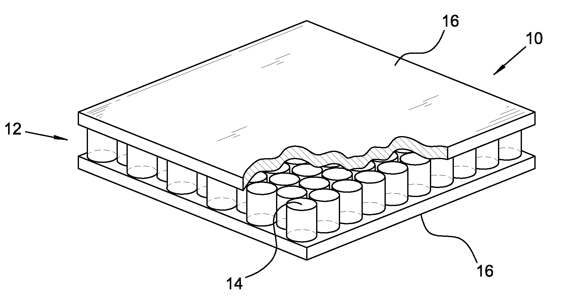
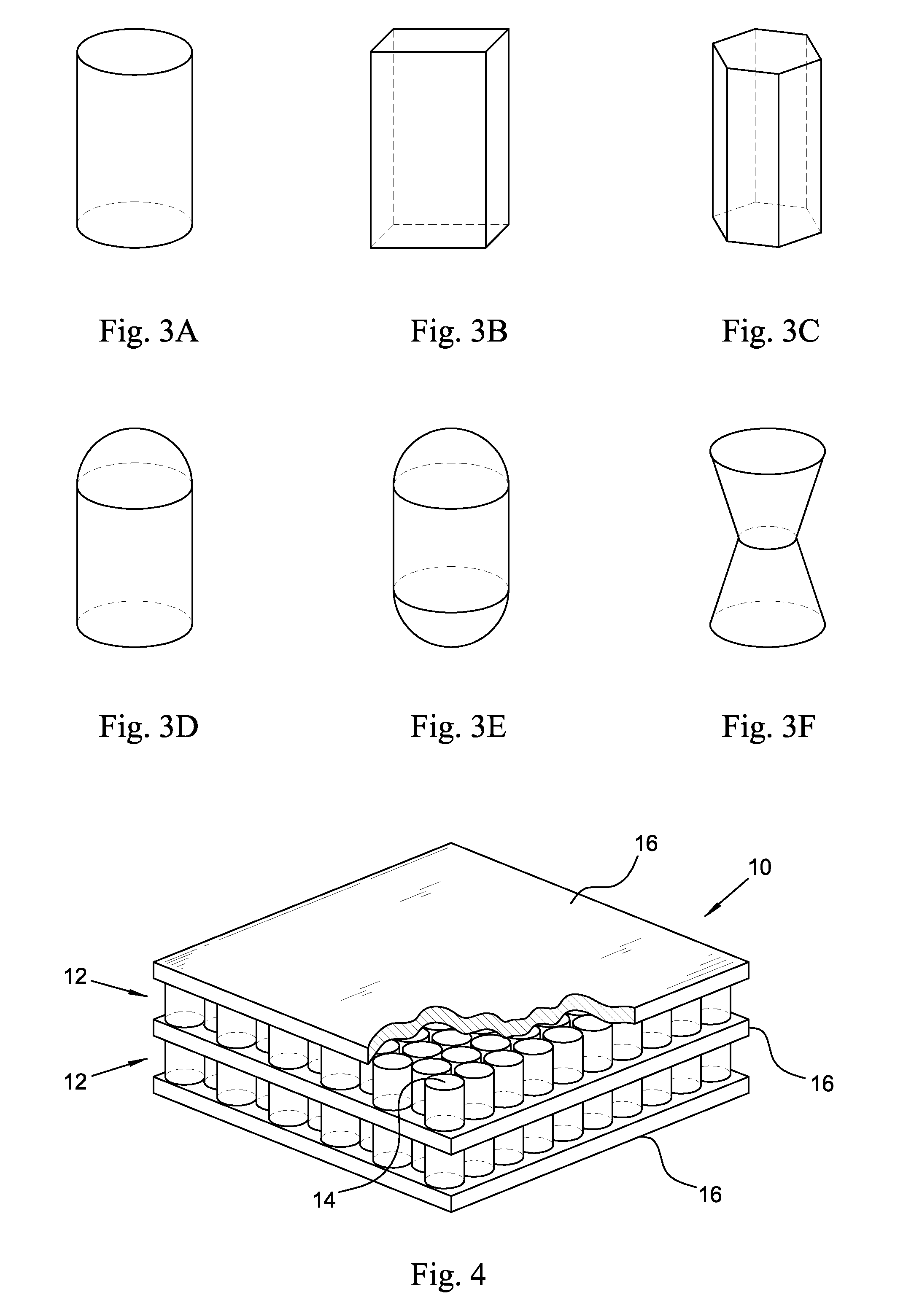
[0040]Two different exemplary radomes implementing a single layer member configuration are built in accordance with two preferred embodiments of the present invention. One of these radomes implements the single main protective layer as is described in FIG. 1 and the other radome implementing a double main protective layer as is described in FIG. 4. The height of the layer members obeys the aforementioned resonant condition h=λg / 2 for a specific resonance frequency. The constraints to the radome design dictated by the resonant effect of the continuous gap may be better explained by reference to FIG. 6. It shows typical plots of transmittance versus normalized operational frequency, measured in resonance frequency units, obtained for both radomes. The plot indicated by 30 represents the single layer configuration whereas the double layer configuration is represented by the plot indicated by 32. Both curves are normalized to have the same transmittance value at the resonance frequency....

example 2

[0041]Exemplary PLMC radomes employing one sided caped cylindrical layer members as is shown in FIG. 5E, to which reference is again made, are built in accordance with a preferred embodiment of the present invention. The height of the layer members is h=0.18 λg, and the radius of the layer members is 0.127 λg. Tuning the operational frequency of such radomes is accomplished by changing either the width of the gap between the layer members of a pair and or by changing the dimensions of the disc. In this specific example, the height of the disc equals the width of the gap such that the disc is in contact with both pair members and the radius of the metal disc is 0.104 λg. A tuning capability of about 20% of the resonance frequency of the radome is demonstrated by reference to FIG. 7. Plots of the transmittance of various radomes versus normalized frequency measured in resonance frequency units are shown. These radomes vary with respect to the size of the respective gaps existing betwe...


PUM

PropertyMeasurementUnit
widthaaaaaaaaaa
wavelengthaaaaaaaaaa
dielectricaaaaaaaaaa

Abstract

A ballistic protective radome (10) consisting of substantially longitudinal layer members (14) firmly and densely packed in a uniform array, forming a main protective layer (12). The layer members (14) are mutually spaced apart and electrically isolated such that a continuous gap (18) is formed in the main protective layer (12). The layer members (14) are made of mechanical energy absorbing and high tensile strength materials such as ceramics, metallic alloys nanoparticulate ceramics and nanoparticulate metallic alloys. The surface of the layer members is electrically conducting, optionally by plating with a layer of highly electrically conducting materials having a width of a few skin depths. Optionally a dielectric layer (16) is attached to at least one surface border of the main protective layer for promoting the ballistic features of the radome and providing for impedance matching. A method for tuning the operational frequency of the radome is provided by grouping the layer members in pairs (12A-12C) of layer members having collinear main axes. Optionally discs (26D-26F) having electrically conducting surface are inserted into the gaps between the paired layer members.

Description

TECHNICAL FIELD OF THE INVENTION[0001]The present invention relates generally to the protection of microwave and millimeter-waves antennae, and more specifically to transparent protective radomes. It also relates to armored plates protecting sensitive equipment from projectiles or other ballistic fragments.BACKGROUND OF THE INVENTION[0002]Radome builders often use impact-resistant laminates for providing ballistic protection to microwave antennae. Typically, laminates made of aramid fibers (Kevlar®) and polyethylene fibers (Spectra®, HDPE) are utilized. International application WO 03 / 031901 discloses a nano-denier fibrous woven sheet that could be used for ballistic impact-resistance radome design. The impact-resistant laminates or woven sheets combined with structural layers of honeycomb or solid foam cores can form basically an almost transparent radome suited to a specific band of frequencies. U.S. Pat. No. 5,182,155 discloses a composite radome structure based on alternate laye...

Claims


Application Information

Patent Timeline
Patent Type & Authority Applications(United States)
IPC IPC(8): H01Q1/42B32B3/22F41H5/04H01Q1/00H01Q15/00
CPCH01Q1/002H01Q1/42F41H5/0492H01Q15/0026H01Q1/422F41H5/04H01Q1/00
Inventor FRENKEL, AVRAHAM
Owner FRENKEL AVRAHAM
Why Eureka
Try Eureka