Phase Plate for Electron Microscope and Method for Manufacturing Same

Inactive Publication Date: 2009-07-02
NAGAYAMA KUNIAKI
View PDF10 Cites 12 Cited by
  • Summary
  • Abstract
  • Description
  • Claims
  • Application Information

AI Technical Summary

Benefits of technology

[0057]17) There is provided the method for manufacturing a phase plate for an electron microscope according to any one of the twelfth to sixteenth inventions, wherein after all the steps have been completed, both surfaces of the phase plate are coated with a nonmagnetic oxidation-resistant conductive thin film, such as a carbon thin film or a noble metal thin film, in order to prevent charging induced by electron beams.
[0058]According to the present invention, phase control of el

Problems solved by technology

However, when electrons pass through a substance, electron scattering occurs, causing an electron beam loss in image formation and deterioration of image intensity.
However, this suggestion also failed to prevent the occurrence of electron beam loss and

Method used


Image

  • Phase Plate for Electron Microscope and Method for Manufacturing Same
  • Phase Plate for Electron Microscope and Method for Manufacturing Same
  • Phase Plate for Electron Microscope and Method for Manufacturing Same

Examples


Embodiment Construction

[0069]The present invention has the above-described features, and the embodiments thereof will be explained below.

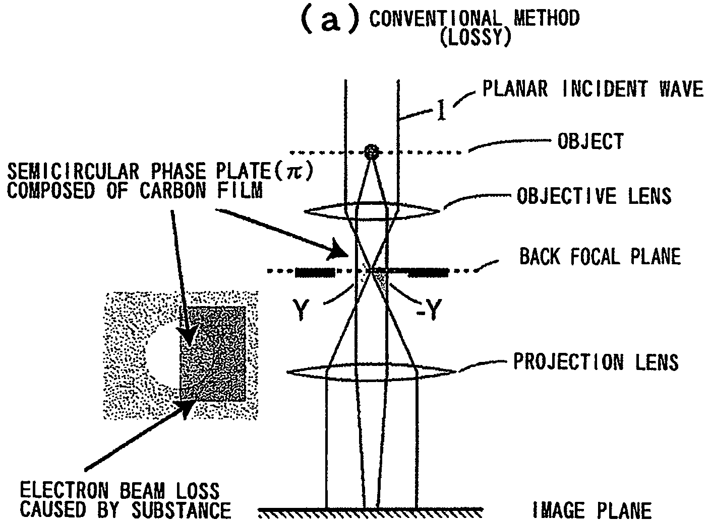
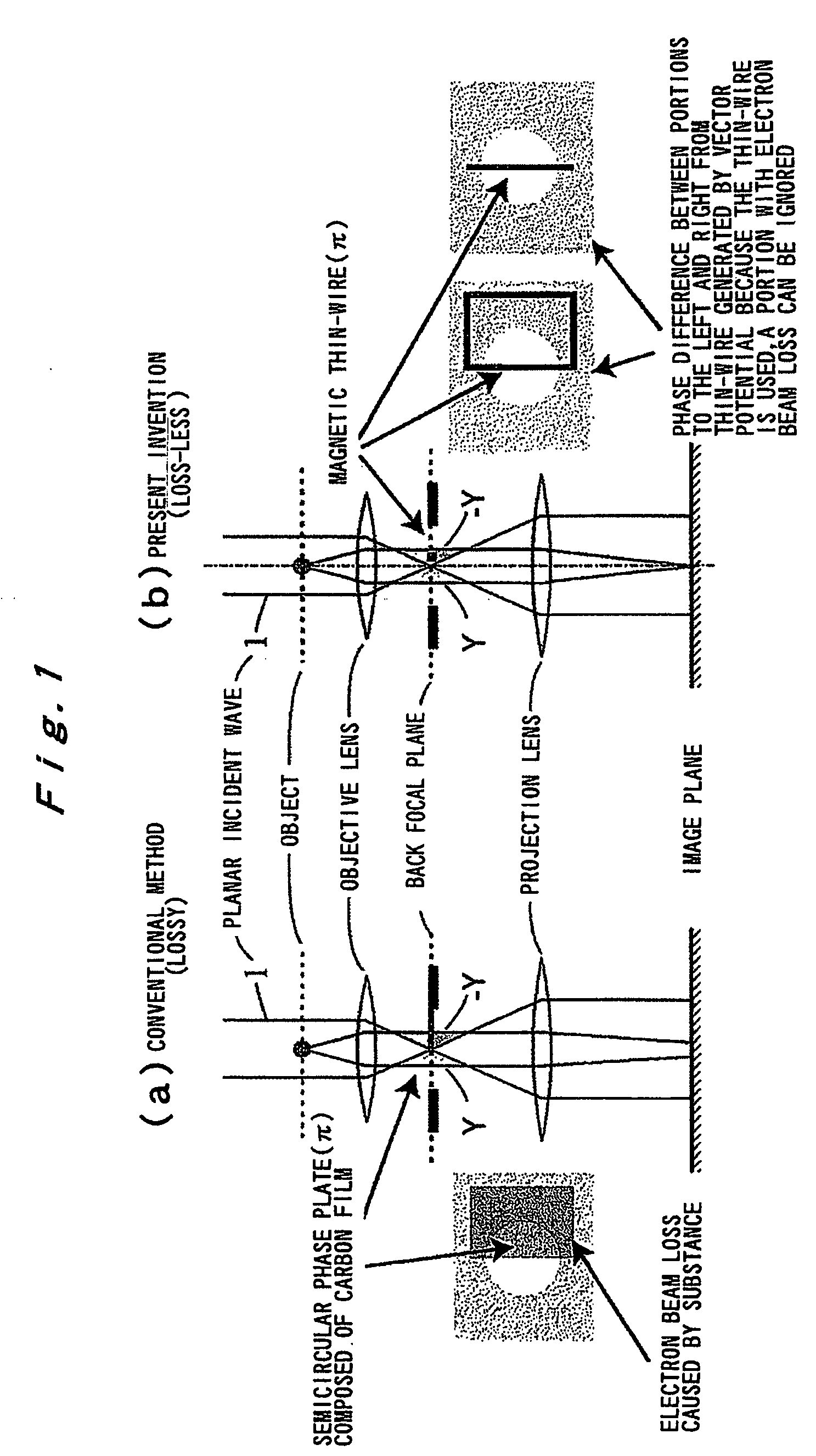
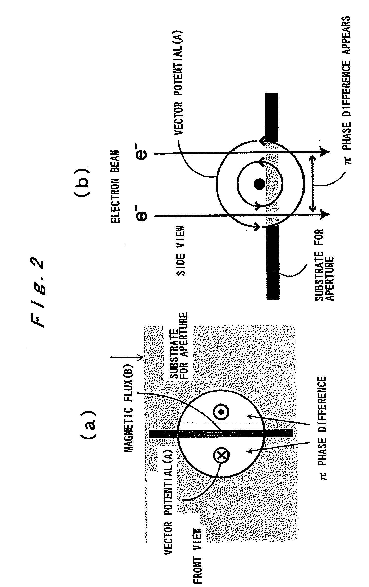
[0070]In the phase plate for an electron microscope of the present invention, a portion of a magnetic thin-wire ring or a magnetic thin-wire rod is caused to span an opening of a support member having the opening, the magnetic thin-wire ring or magnetic thin-wire rod generates a vector potential, and a phase difference is formed between electron beams that will pass on both sides of a spanning portion of the magnetic thin-wire ring or the magnetic thin-wire rod.

[0071]In the conventional phase plate, for example, such as described in Japanese Patent Application Laid-open No. 2003-100249 a phase shift is used that is created by an internal electrostatic potential produced by a substance, but in the phase plate of the present invention, a phase shift of an electron wave created by a vector potential is used. As a result, in the phase plate of the present invention, a magnet...


PUM


Abstract

A phase plate for an electron microscope in which a portion of a magnetic thin-wire ring or a magnetic thin-wire rod (15) spans an opening of a support member (14) having the opening, the magnetic thin-wire ring or magnetic thin-wire rod (15) generates a vector potential, and a phase difference is formed between electron beams that pass through left and right sides of a spanning portion of the magnetic thin-wire ring or the magnetic thin-wire rod (15). The phase plate prevents the electron beam loss more effectively, can be applied at an accelerating voltage within a wide rage from a low voltage to a high voltage, causes no difficulties in production, has good utility, and makes it possible to obtain a high-contrast image.

Description

TECHNICAL FIELD[0001]The present invention relates to a phase plate for an electron microscope and to a method for manufacturing the phase plate. More particularly, the present invention relates to a novel phase plate for an electron microscope that prevents the electron beam loss and to a method for manufacturing the phase plate.BACKGROUND ART[0002]An internal electric potential of a substance has been used as a source of phase change in phase plates of electron microscopes. However, when electrons pass through a substance, electron scattering occurs, causing an electron beam loss in image formation and deterioration of image intensity. To alleviate this effect, the inventors of the present invention suggested to use a light element (for example, carbon) as a phase plate (Japanese Patent Applications Laid-open Nos. 2001-273866 and 2003-100249). However, this suggestion also failed to prevent the occurrence of electron beam loss and lacked utility at an accelerating voltage of 100 k...

Claims


Application Information

Patent Timeline
IPC IPC(8): G02F1/01G01N23/00
CPCH01J37/26H01J2237/2614H01J2237/1514H01J37/295
Inventor NAGAYAMA, KUNIAKI
Owner NAGAYAMA KUNIAKI
Why Eureka
Try Eureka