
Flow-through cell and method of use

a flow-through cell and flow-through technology, applied in the field of flow-through cells, can solve the problems of difficult inspection, increased risk of error, laborious laboratory microscopy techniques, etc., and achieve the effect of reducing cross-contamination between channels and optical discontinuities

Inactive Publication Date: 2009-07-02
PARKER HANNIFIN LTD HEMEL HEMPSTEAD
View PDF13 Cites 8 Cited by
  • Summary
  • Abstract
  • Description
  • Claims
  • Application Information

AI Technical Summary

Benefits of technology

[0010]Thus, particles such as micro-organisms can be retained within the channel where they can be optically detected by optical detection means. Particles, such as micro-organisms can thereby be concentrated from a large volume sample. This can improve the sensitivity of the technique and / or its efficiency in analysing large volume samples. The presence of liquid-permeable particle retaining means may allow other liquids to be passed through the channel, after the sample, without loss of particles, to enable a variety of analytical procedures. For example, a stain or label, such as an immunofluorescent label, may be passed through the channel, from the inlet to the outlet, optionally followed by a wash step, allowing retained particles, such as micro-organisms, to be stained or labelled.
[0029]The substrate may comprise first and second substrate portions which together define the or each channel. Preferably, the first and second substrate portions comprise planar surfaces in contact with each other. One of the substrate portions may comprise one or more elongate indentations which, in combination with the other substrate portion, defines one or more enclosed channels. One of the substrate portions may include one or more grooves on a surface thereof which, in combination with the other substrate portion, define the channel or channels. The grooves may have been formed by etching of the substrate. The same substrate portion, or preferably the other substrate portion, may have one or more holes therethrough which function as the inlet or inlets. Preferably, each of the first and second substrate portions are continuous. By providing continuous substrate portions, optical discontinuities which would affect optical analysis are minimised.

Problems solved by technology

Manual laboratory microscopy techniques are laborious, particularly when an analyst is looking for a very low concentration of micro-organisms.
However, any micro-organisms in the sample which is to be analysed will be spread out across a large surface area requiring time consuming automatic scanning and increasing the risk that an error will be made.
However, only a small proportion of the micro-organisms which pass through the described apparatus will be identified and there is no mechanism provided to retain the detected micro-organisms, making it difficult to check results.

Method used


Image

  • Flow-through cell and method of use
  • Flow-through cell and method of use
  • Flow-through cell and method of use

Examples


Embodiment Construction

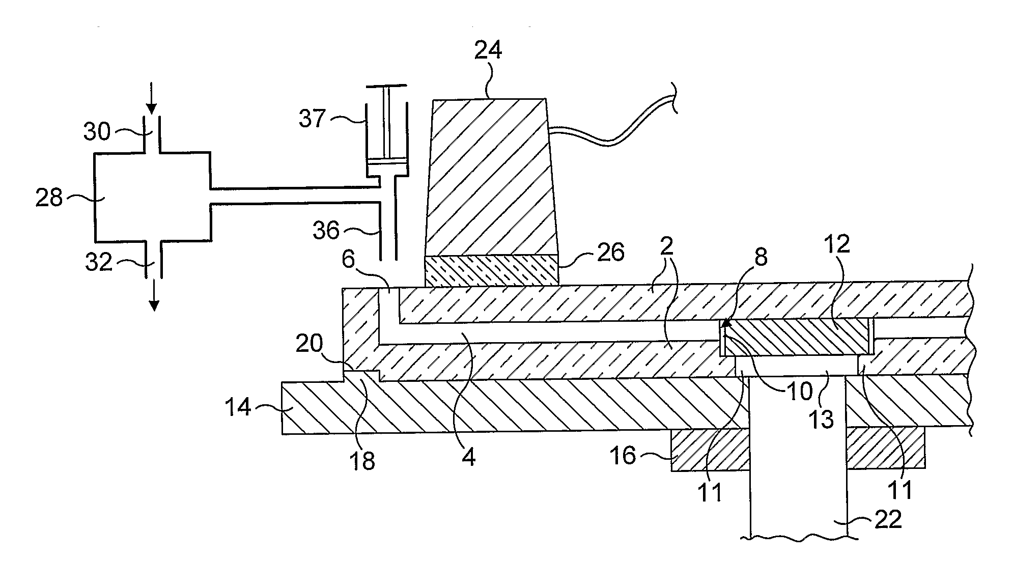
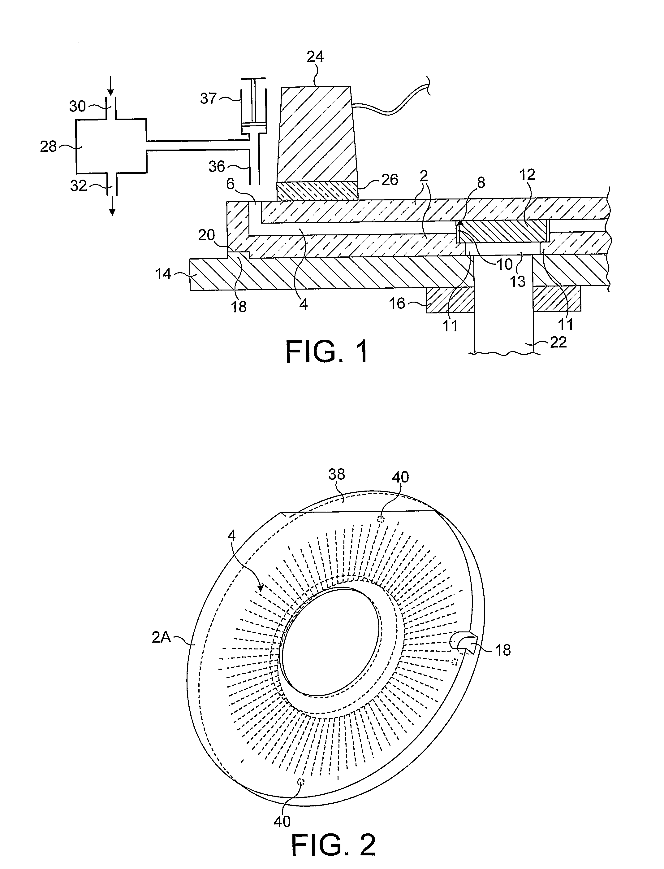
[0067]FIG. 1 is a cross-section through a system comprising detection apparatus and a flow-through cell according to the present invention. A flow-through cell 1 comprises a transparent glass substrate 2 which defines a plurality of channels 4, one of which is shown in full. The flow-through cell is made from a high quality optical glass and is substantially planar, allowing it to be used as a microscope slide. Each channel has an inlet 6 and outlet 8. Each channel is around 100 microns wide and 40 microns high. 40 microns is a capillary dimension which causes the substrate to draw a liquid sample introduced through the inlet into the channel.

[0068]Each outlet is covered by a size exclusion filter membrane 10 which functions as means to allow the flow of a liquid sample through the channel from the inlet to the outlet while retaining particles (in this case micro-organisms) from the liquid sample whose dimensions exceed threshold dimensions within the channel. A wick 12, such as a b...


PUM


Abstract

There is disclosed a flow-through cell comprising a substrate defining a channel, having an inlet and an outlet, at least a portion of the substrate being light-permeable to allow particles within at least a portion of the channel between the inlet and the outlet to be optically detected through the substrate, wherein the flow-through cell comprises liquid-permeable particle retaining means located downstream of the at least a portion of the channel where particles can be optically detected, for allowing the flow of a liquid sample through the channel from the inlet to the outlet while retaining particles from the liquid sample whose dimensions exceed threshold dimensions within the channel, where they can be optically detected. The flow-through cell is particularly applicable to the detection of micro-organisms in drinking water.

Description

FIELD OF THE INVENTION[0001]The invention relates to a flow-through cell which is useful for the detection of particles in general and micro-organisms in particular.BACKGROUND TO THE INVENTION[0002]Issues relevant to the invention will now be discussed with reference to the example application of detecting Cryptosporidium oocysts in drinking water, although the same principles apply to the detection of other particles and other micro-organisms in other media.[0003]It is important for public health to screen drinking water for pathogenic micro-organisms such as the protozoa Cryptosporidium and Giardia Lamblia. Because these micro-organisms can be pathogenic in minute quantities, it is advantageous to provide a highly sensitive test capable of screening large liquid samples.[0004]It is known to detect these protozoa by optical microscopy on dry mounted slides, using fluorescent markers which bind specifically to Cryptosporidium oocysts or Giardia cysts or techniques such as differenti...

Claims


Application Information

Patent Timeline
IPC IPC(8): C12Q1/04C12M1/34
CPCB01L3/5025B01L3/50273B01L3/502753B01L2300/0681B01L2300/0803B01L2300/0877G01N2035/00564B01L2400/0406G01N1/40G01N15/1463G01N15/1484G01N35/00029G01N2001/4088B01L2300/0887G01N15/1433C12Q1/06G01N21/05
Inventor SHAW, GARY OWEN
Owner PARKER HANNIFIN LTD HEMEL HEMPSTEAD
Learn More