System for fermentation using algae

a technology of algae and fermentation system, which is applied in the direction of specific use of bioreactor/fermenter, microorganisms, after-treatment of biomass, etc., can solve the problems of slow conversion of raw organic material into product, small amount of catalytic microorganisms present in the reactor, and low reaction ra

Active Publication Date: 2009-07-02
MISSING LINK TECH
View PDF9 Cites 29 Cited by
  • Summary
  • Abstract
  • Description
  • Claims
  • Application Information

AI Technical Summary

Benefits of technology

[0024]The continuous stirred tank reactor has an inlet and an outlet, and the plug flow reactor has an inlet and outlet. The inlet of the plug flow reactor is in fluid communication with the outlet of the continuous stirred tank reactor. The first baffle separating the continuous stirred tank reactor and the plug flow reactor is movable and has an opening therein, and the opening is coincident with the outlet

Problems solved by technology

First, when the raw organic material is first introduced into the fermentation reactor, there is only a small amount of catalytic microorganisms present in the reactor.
Thus, the conversion of the raw organic material into prod

Method used


Image

  • System for fermentation using algae
  • System for fermentation using algae
  • System for fermentation using algae

Examples


embodiment 110

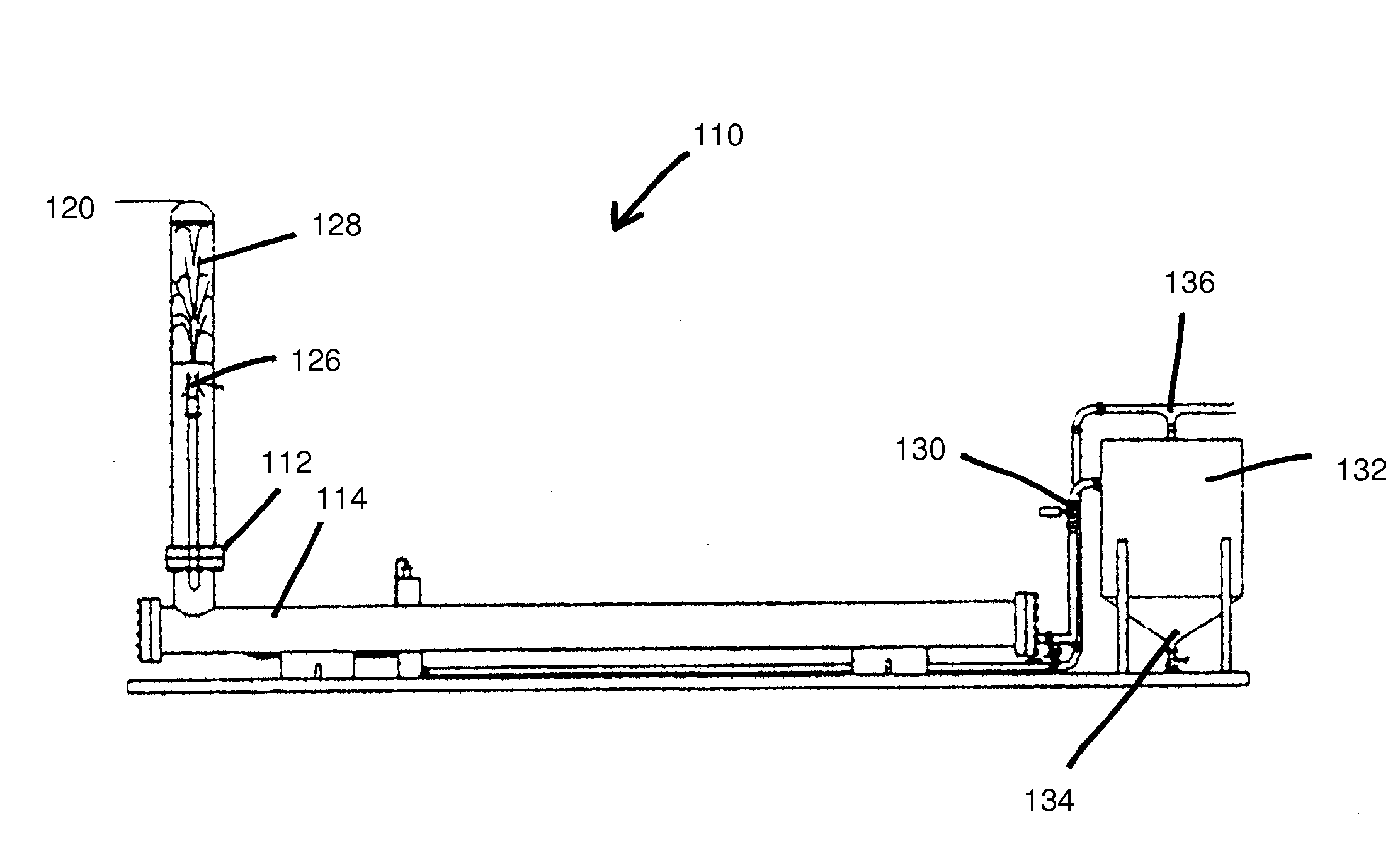
[0040]FIGS. 3-5 show another embodiment 110 of the system of the present invention mounted on a platform 111. Instead of a single fermentation reactor 10, this embodiment has a first reactor 112 and a second reactor 114. The first reactor 112 has a generally cylindrical shape and a biomass inlet 116. The biomass inlet 116 receives the processed biomass stream, such as algae, from a bioreactor 117 through a pump 115 into the first reactor 112. The second reactor 114 is in fluid communication with the first reactor 112 and is placed in an orthogonal relationship to the first reactor 112. A first valve means 118 placed between the first reactor 112 and the second reactor 114 controls fluid flow between the first reactor 112 and the second reactor 114.

[0041]The biomass stream entering the first reactor 112 has gas injected therein through a gas inlet 120 in fluid connection with the first reactor 112. The gas inlet 120 is located at one end of the first reactor 112, and the biomass inle...

first embodiment

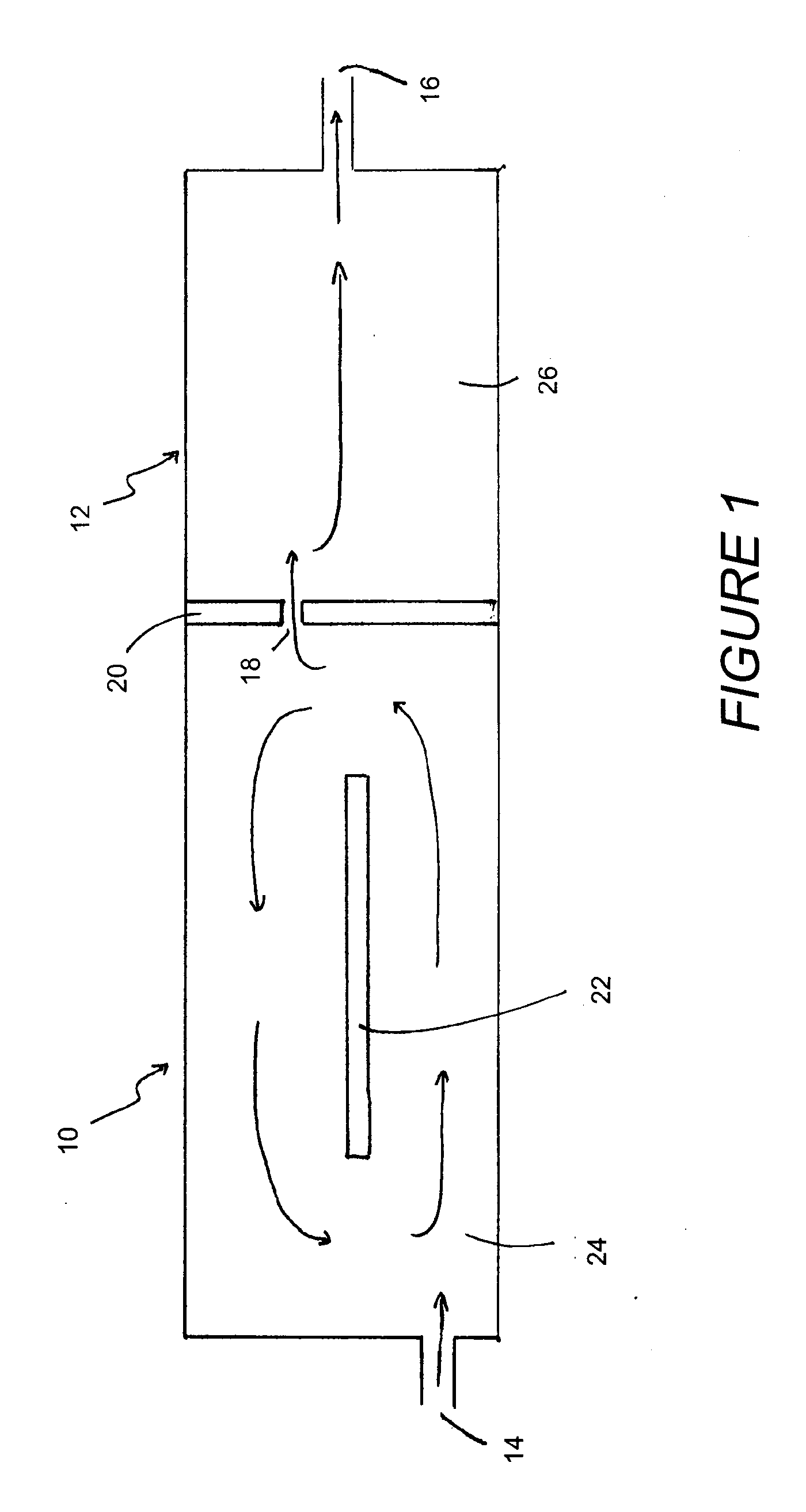
[0043]The present invention achieves up to 80% reduction in the operating costs of a batch fermentation processes because the process is continuous. The fermentation reactor of the first embodiment optimizes fermentation reaction between the first and second sections. The system applies to fermentation of any raw organic material and adjusts the first and second section for an optimal reactor for any given set of operating conditions.

[0044]Additionally, the present invention provides an efficient resource for production of oil, an alternative to naturally occurring oil that must be harvested from the Earth. The present invention uses the biological processing of microorganisms, specifically algae, to process waste products, while creating usable resources. The present invention allows for the efficient or maximized collection of oil from the biological processing.


PUM


Abstract

The system for fermentation using algae of the present invention includes a first reactor and a second reactor being in fluid communication with each other. A first valve placed between the first reactor and the second reactor controls the fluid connection between the reactors. A gas inlet, in fluid connection to the first reactor, is located at an end opposite the second reactor. A devolatization unit or cell lysis chamber is connected to the second reactor by a second valve. A biomass stream having gas, liquid and biosolids contents passes through the first reactor with gas. The biomass stream mixes and dissolves the gas in the reactors. The cellular structure of the biomass stream ruptures in the devolatization unit, allowing the processed materials, such as oil, gas, and biosolids, to be harvested for use.

Description

RELATED U.S. APPLICATIONS[0001]Not applicable.STATEMENT REGARDING FEDERALLY SPONSORED RESEARCH OR DEVELOPMENT[0002]Not applicable.REFERENCE TO MICROFICHE APPENDIX[0003]Not applicable.BACKGROUND OF THE INVENTION[0004]1. Field of the Invention[0005]The present invention relates to systems for fermentation. More particularly, the present invention relates to systems for fermentation using algae as the microorganism.[0006]2. Description of Related Art[0007]Including Information Disclosed Under 37 CFR 1.97 and 37 CFR 1.98.[0008]From the simplest to the most complex, biological processes maybe classified as fermentation, elementary physiological processes, and the action of living organisms. Fermentation is a biological reaction whereby a raw organic material is converted into a product by the action of microorganisms or by the action of enzymes produced by microorganisms. In atypical fermentation reaction, a raw organic material is fed into a reactor. The raw organic material can be any ...

Claims


Application Information

Patent Timeline
IPC IPC(8): C12N1/12C12M1/00
CPCC12M21/02C12M27/20C12N1/12C12M47/02C12M47/06C12M43/06
Inventor SHEPHERD, SAMUEL L.MCCALL, JERRY
Owner MISSING LINK TECH
Why Eureka
Try Eureka