Multiwell incubation apparatus and method of analysis using the same

a technology of incubation apparatus and multi-well, which is applied in the direction of lighting and heating apparatus, laboratory glassware, library screening, etc., can solve the problem of complex manipulation and achieve the effect of reducing the size of the apparatus

Inactive Publication Date: 2009-07-02
INTER UNIV RES INST RES ORG OF INFORMATION & SYST
View PDF10 Cites 4 Cited by
  • Summary
  • Abstract
  • Description
  • Claims
  • Application Information

AI Technical Summary

Benefits of technology

[0019]With the incubation apparatus according to the present invention, a temperature series of equal intervals can be provided between the highest temperature and a temperature which is the lowest in a predetermined temperature range. Therefore, in a single run of incubation, several hundreds of experiments can be performed. Moreover, the user does not need to move the incubation apparatus before carrying out an analysis. In addition, since the problem of water evaporation from wells on the high temperature side and condensation on the low temperature side is eliminated, temperature-gradient culturing can be continued for a prolonged period of time, with small volumes of specimens. Therefore, the apparatus size can be reduced, and in addition, stacking of a number of such apparatus one on another enables the user to analyze the specimens under thousands of different conditions simultaneously. Furthermore, since the liquid or gas flow channel or bath is provided for each well row with an aim to regulate vapor pressure, a uniform temperature can be realized within a transverse row. When argon gas or nitrogen gas is allowed to flow through the flow channel, oxygen partial pressure in a well can be regulated, and likewise, partial pressure of a specific gas can be easily modified so as to provide a plurality of partial pressure conditions.
[0020]Therefore, the incubation apparatus according to the present invention enables culturing of microbes under different temperature conditions, which has previously been difficult, enables the user to find optimal culture temperatures, and realizes proliferation of microorganisms whose temperature conditions are unknown.

Problems solved by technology

However, when incubation is performed under a variety of different temperature conditions, intricate manipulation is required.
Moreover, for performing analyses, the multiwell plates must be taken out of the incubation apparatuses, which is also inconvenient.

Method used


Image

  • Multiwell incubation apparatus and method of analysis using the same
  • Multiwell incubation apparatus and method of analysis using the same
  • Multiwell incubation apparatus and method of analysis using the same

Examples


example 1

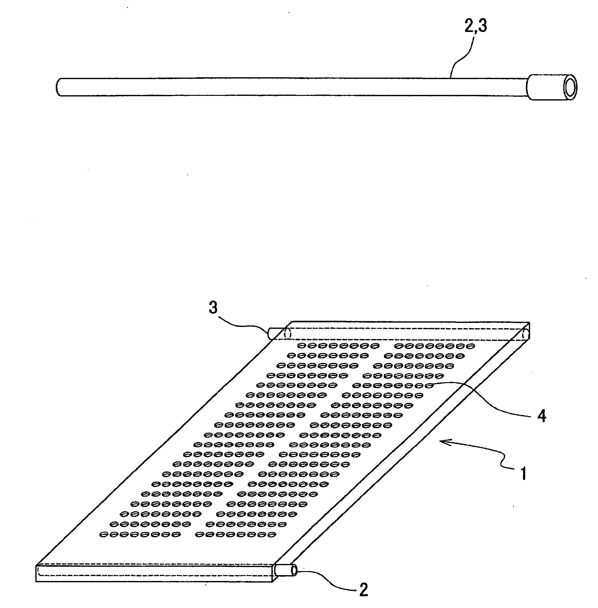
[0102]As an incubation apparatus of the present invention, a housing vessel 1 as shown in FIG. 1 was produced. The outer dimensions of the vessel 1, made of aluminum plates, are 347 mm×222 mm×20 mm.

[0103]Each well socket 4 has a diameter of 6 mm and a depth of 13 mm.

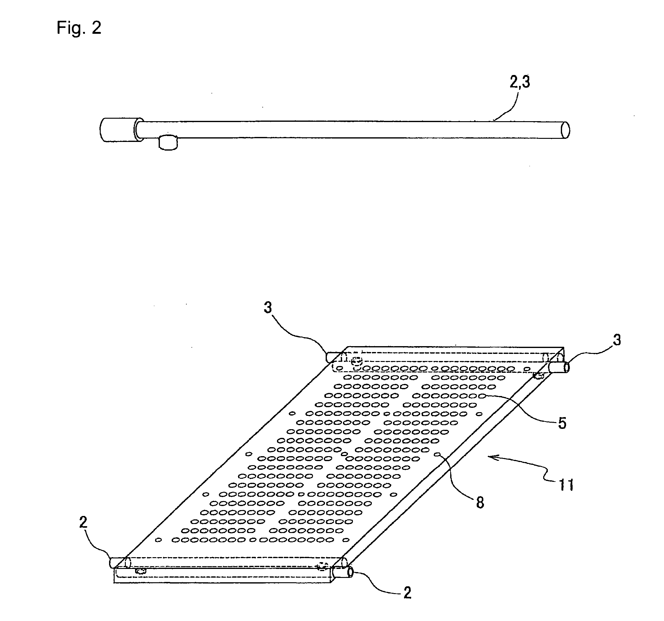
[0104]As shown in FIG. 1, a flow channel 2 in the form of a single pipe is provided so as to run along and penetrate through one side of the apparatus. The pipe is made of aluminum and has an inner diameter of 8 mm. The flow channel 2 is connected to a tube extending from a thermostatic bath and also to another tube going back to the thermostatic bath, whereby water of a constant temperature can be circulated. The same situation applies to a flow channel 3.

[0105]With this configuration, the temperature of the incubation apparatus gradually changes from the highest temperature at the vicinity of the flow channel 3 to the lowest temperature at the vicinity of the flow channel 2, thereby attaining a plurality of incubation ...

example 2

[0107]Similar to Example 1, another incubation apparatus was produced, wherein, instead of the section shown in FIG. 12 of the incubation apparatus of Example 1, a section shown in FIG. 13 was employed.

example 3

[0108]Similar to Example 1, yet another incubation apparatus was produced, wherein, instead of the section shown in FIG. 12 of the incubation apparatus of Example 1, a section shown in FIG. 14 was employed.


PUM

PropertyMeasurementUnit
inner diameteraaaaaaaaaa
depthaaaaaaaaaa
inner diameteraaaaaaaaaa

Abstract

A continuous temperature-gradient incubation apparatus designed to solve the problem of moving of liquid vapor generated on the high-temperature side toward the low-temperature side to thereby cause condensation.There is provided a multiwell incubation apparatus having a well-housing vessel made of a heat conducting material and, detachably housed therein, liquid-storing wells, the wells being arranged in transverse rows and longitudinal rows, the multiwell incubation apparatus being also provided with a liquid or gas flow channel or bath for supply of a gas saturated with vapor of the liquid, the multiwell incubation apparatus being capable of maintaining incubation temperatures differing between individual transverse rows of wells with a predetermined temperature difference, so as to realize a temperature series which forms a predetermined temperature difference profile along the longitudinal rows, characterized in that the multiwell incubation apparatus includes a heat source for realizing a temperature which is the lowest in the given temperature series, the heat source being disposed outside the well rows and along the transversely lined up wells close to a first side of the housing vessel; another heat source for realizing a temperature which is the highest in the given temperature series, the heat source being disposed outside the well rows and along a side opposite to the first side; and a separator provided for each transverse row of a certain temperature.

Description

FIELD OF THE INVENTION[0001]The present invention relates to a multiwell incubation apparatus which provides, in a single apparatus, a plurality of different incubation temperatures within a predetermined temperature range, and to a method of analysis using such an apparatus.BACKGROUND OF THE INVENTION[0002]Analyses using microbial cells or other biological specimens have been performed, for example, by inoculating microbes on an agar medium and observing them by the naked eye after they are maintained for a certain period of time at a constant temperature in an incubator. In recent years, however, liquid culture has become more popular, which employs a multiwell plate having a plurality of wells. Moreover, for chemical reactions involved in, for example, combinatorial chemistry, multiwell plates are often used to perform analysis of many specimens.[0003]Usually, the above-mentioned liquid culture and specimen analyses are performed as follows: Specimens are added to the wells of a ...

Claims


Application Information

Patent Timeline
Patent Type & Authority Applications(United States)
IPC IPC(8): C40B30/00C40B60/00C40B99/00
CPCB01F11/0017B01L3/50853B01L7/54B01L2300/0654B01L2300/0829C12M41/14B01L2300/1883C12M23/12C12M27/16C12M37/00B01L2300/185B01F31/23C12M1/18C12M1/34C12N1/00C12Q1/02
Inventor SHIMAMOTO, NOBUO
Owner INTER UNIV RES INST RES ORG OF INFORMATION & SYST
Why Eureka
Try Eureka