Information Processing Apparatus and Semiconductor Storage Drive
- Summary
- Abstract
- Description
- Claims
- Application Information
AI Technical Summary
Benefits of technology
Problems solved by technology
Method used
Image
Examples
first embodiment
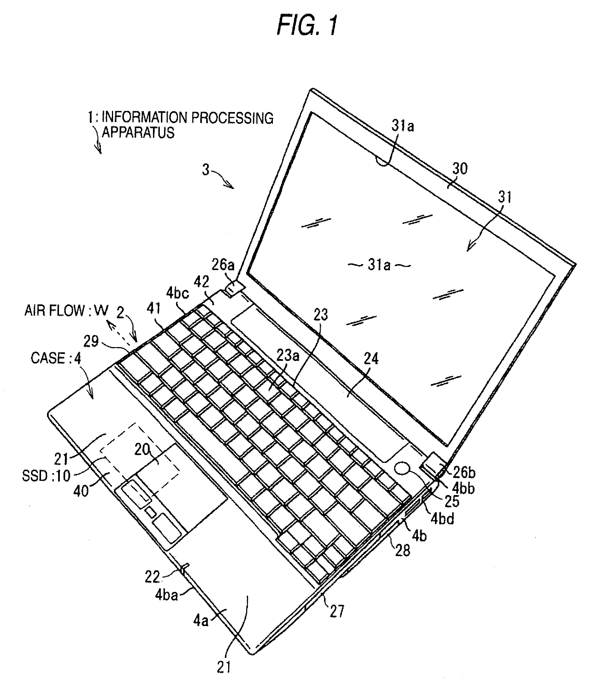
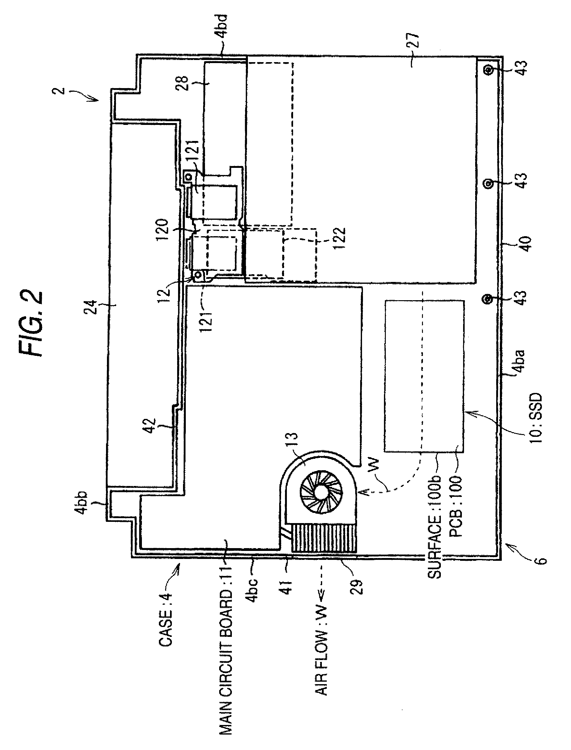
[0025]FIG. 1 is a schematic diagram illustrating the appearance of an information processing apparatus according to a first embodiment of the invention. An information processing apparatus 1 is configured to include a main unit 2 and a display unit 3 attached to the main unit 2.
[0026]The main unit 2 includes a box-shaped case 4, and the case 4 is provided with an upper wall 4a, a peripheral wall 4b, and a lower wall 4c. The upper wall 4a of the case 4 has a front portion 40, a middle portion 41, and a back portion 42 sequentially from the side near a user who operates the information processing apparatus 1. The lower wall 4c faces a placement surface on which the information processing apparatus 1 is placed. The peripheral wall 4b has a front wall 4ba, a rear wall 4bb, and side walls 4bc and 4bd on the left and right sides.
[0027]The front portion 40 includes a touch pad 20 that is a pointing device, a palm rest 21, and an LED 22 that is lighted in synchronization with an operation o...
second embodiment
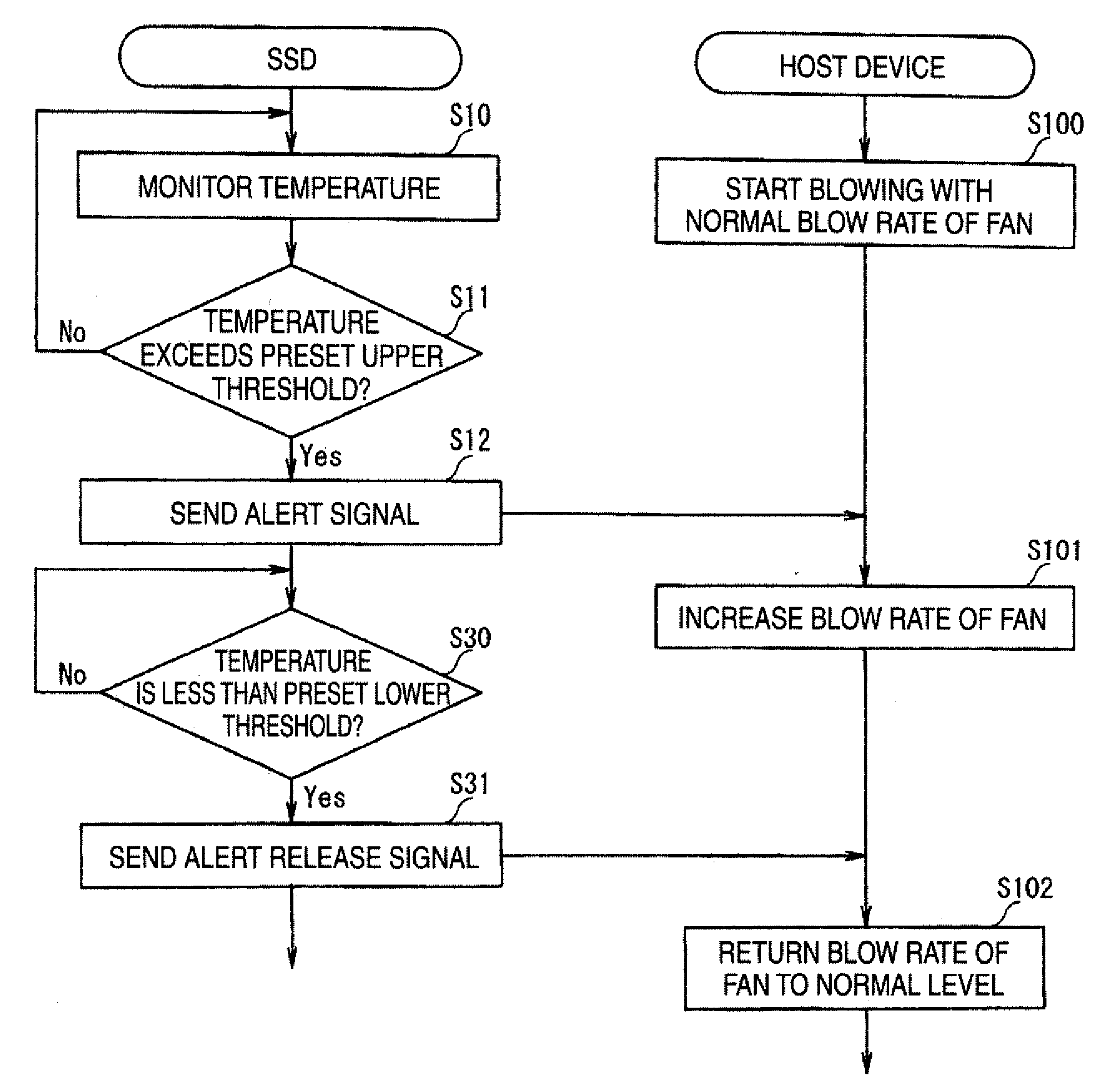
[0077]FIG. 8 is a block diagram showing a general configuration of an information processing apparatus according to a second embodiment of the present invention. Unlike the first embodiment in which the SSD 10 performs the operation to suppress its own measured temperature to be less than the upper threshold, in the second embodiment, the host device 8 connected the SSD 10 performs a cooling operation to cool the SSD 10 based on temperature information outputted from the SSD 10.
[0078]In other words, the information processing apparatus 1 of the second embodiment has the same configuration and function as the information processing apparatus 1 of the first embodiment except that a CPU 115 of the second embodiment has a control circuit 115a to control a cooling operation.
[0079]The control circuit 115a makes a blow rate of a fan 13 larger than that in a normal operation for cooling the SSD 10 based on the temperature information outputted from the SSD 10. In this embodiment, since the ...
third embodiment
[0087]FIG. 10 is a flow chart illustrating an operation of an information processing apparatus according to a third embodiment of the present invention. The control circuit 115a of the third embodiment has the same configuration and function as that of the second embodiment except that the former has a processing power of the host device 8 to decrease the number of clocks as a cooling operation.
[0088]The control circuit lSa starts an operation of the host device 8 with the normal number of clocks of the CPU 115 (Step S110). Next, upon receiving the alert signal from the SSD 10, the control circuit 115a decreases the number of clocks of the CPU 115 (Step 3111) below the normal number. Upon receiving the alert release signal from the SSD 10, the control circuit 115a returns the number of clocks of the CPU 115 to the normal number (Step S112).
[0089]In addition, the control circuit 115a may control the number of clocks of either both of the CPU 115 and the GPU 116 or only the GPU 116.
[0...
PUM
 Abstract
Description
Claims
Application Information
 - R&D
- Intellectual Property
- Life Sciences
- Materials
- Tech Scout
- Unparalleled Data Quality
- Higher Quality Content
- 60% Fewer Hallucinations
Browse by: Latest US Patents, China's latest patents, Technical Efficacy Thesaurus, Application Domain, Technology Topic, Popular Technical Reports.
© 2025 PatSnap. All rights reserved.Legal|Privacy policy|Modern Slavery Act Transparency Statement|Sitemap|About US| Contact US: help@patsnap.com


