Active thermal energy storage system and tank for use therein

a technology of active thermal energy storage and active heat transfer, which is applied in the direction of lighting and heating apparatus, heating types, greenhouse gas reduction, etc., can solve the problems of providing energy, and achieve the effect of facilitating the use of excess electrical energy off-peak

Inactive Publication Date: 2009-07-09
ELCAL RES LLC
View PDF11 Cites 59 Cited by
  • Summary
  • Abstract
  • Description
  • Claims
  • Application Information

AI Technical Summary

Benefits of technology

[0008]The ATESS facilitates the use of off peak excess electrical energy, thus reducing the need for oil and natural gas systems that are typically used for air and hot water heating in residential dwellings or commercial buildings. Thus, the invention relates to the active transfer of thermal heat energy obtained from any of a variety of natural energy sources (e.g., solar, electrical, wind, gas, oil, etc.) to a thermal energy storage material, such as one of the materials described in U.S. Pat. No. 3,976,584 to Leifer, the entire contents of which patent is incorporated herein. The thermal energy storage material may be contained in an appropriate tank or storage vessel (which will be described in greater detail below). The energy stored in the thermal energy storage material may be transferred by an active heat transfer system (e.g., a heat pump) to any of a variety of locations within a residential home or commercial building as needed for air and/or water heating at any time during a 24 hour day.
[0009]The ATESS operates on the principal of collecting limited available input energy from any and all sources (e.g., solar, electricity, wind, oil, gas) and storing that energy in a thermal energy storage material until needed later. The energy stored in the thermal energy storage material may be removed by a heat transfer system (e.g., heat pump) to control the temperature of residential homes or comme...

Problems solved by technology

However, such systems can only prov...

Method used


Image

  • Active thermal energy storage system and tank for use therein
  • Active thermal energy storage system and tank for use therein
  • Active thermal energy storage system and tank for use therein

Examples


Embodiment Construction

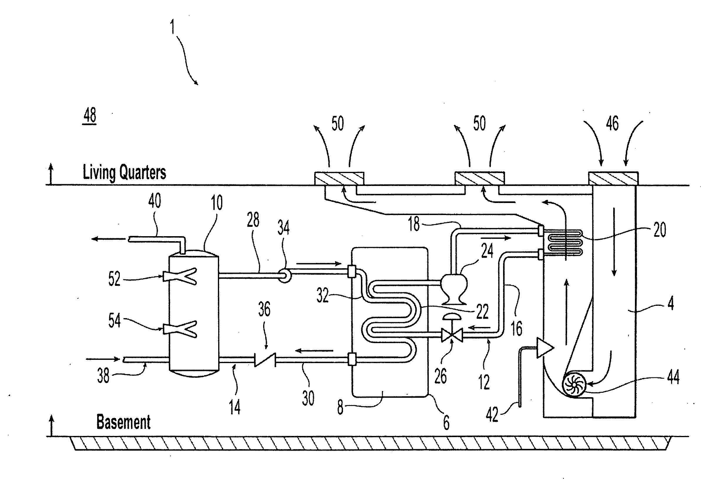
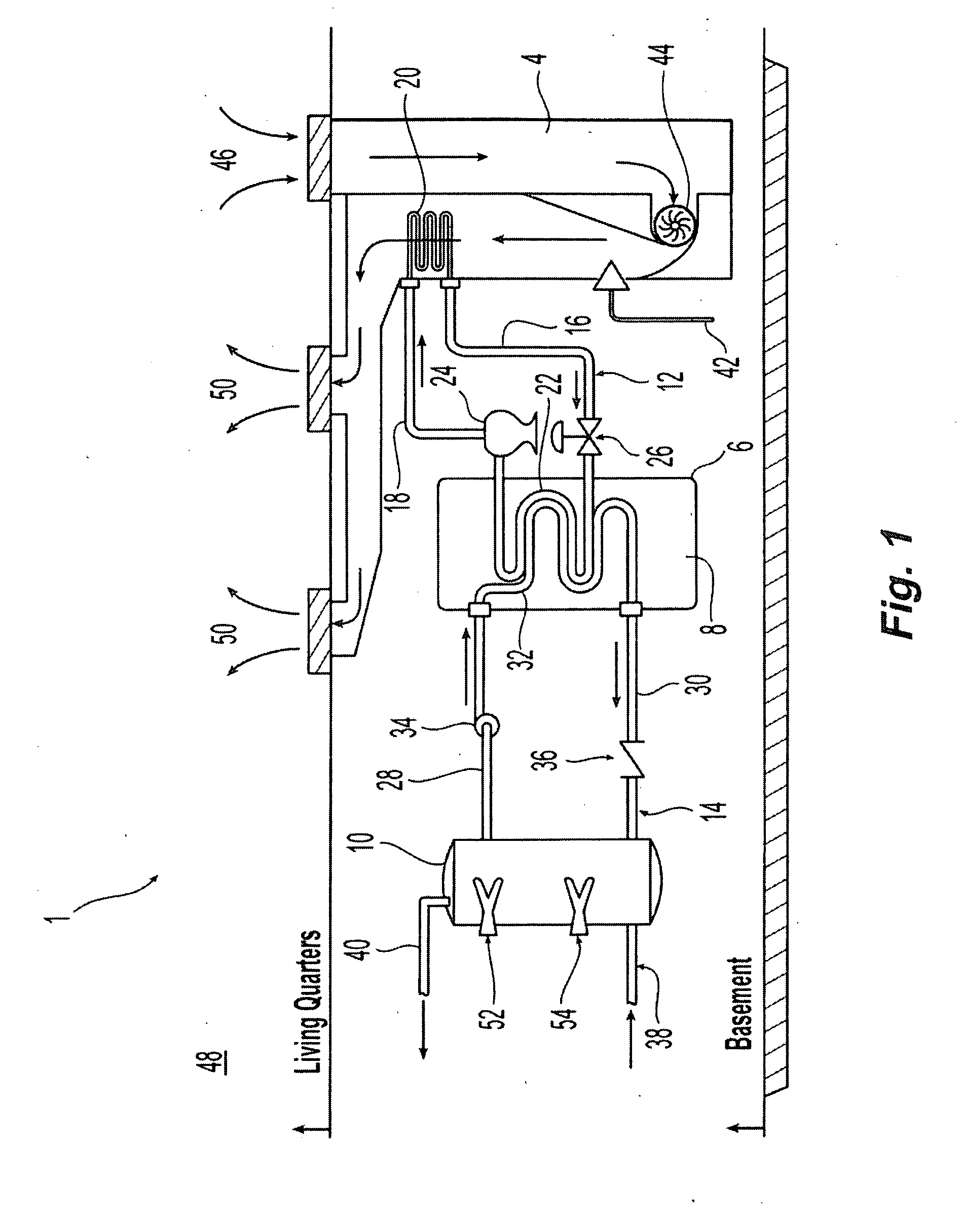
[0029]As previously noted, there are many sources of energy (e.g., solar, electrical, oil, gas, wind, etc.) which may be available for collection only during limited time periods during a 24 hour day. This is in contrast to the electrical, heating or cooling power needs associated with a residential or commercial building, which may vary during any given 24 hour period. The disclosed ATESS accommodates such limited availability of these energy sources and provides a steady source of energy, as needed, throughout a 24 hour period.

[0030]Referring to FIG. 1, the ATESS 1 is shown installed in the basement area 2 of a dwelling having an oil or natural gas hot air furnace system 4. The ATESS 1 may comprise a storage tank 6 containing a quantity of thermal energy storage material 8, a hot water storage tank 10 for heating and distribution of hot water through the residence, and a connection 12 between the storage tank 6 and the furnace system 4 to allow the transfer of heat between the the...


PUM


Abstract

An active thermal energy storage system is disclosed which uses an energy storage material that is stable at atmospheric pressure and temperature and has a melting point higher than 32 degrees F. This energy storage material is held within a storage tank and used as an energy storage source, from which a heat transfer system (e.g., a heat pump) can draw to provide heating of residential or commercial buildings and associated hot water. The energy storage material may also accept waste heat from a conventional air conditioning loop, and may store such heat until needed. The system may be supplemented by a solar panel system that can be used to collect energy during daylight hours, storing the collected energy in the energy storage material. The stored energy may then be used during the evening hours to heat recirculation air for a building in which the system is installed.

Description

CROSS-REFERENCE TO RELATED APPLICATIONS[0001]This application is a continuation-in-part of co-pending U.S. non-provisional patent application Ser. No. 12 / 212,822, filed Sep. 18, 2008, which is a continuation of U.S. non-provisional patent application Ser. No. 11 / 818,401, filed Jun. 13, 2007, now U.S. Pat. No. 7,441,558, which is a non-provisional of U.S. provisional patent application Ser. No. 60 / 852,844, filed Oct. 19, 2006, the entirety of which applications are incorporated herein by reference.FIELD OF THE INVENTION[0002]The invention relates to a system for heating and cooling of residential and commercial building spaces and hot water systems, and more particularly to an active heat transfer system used for use in efficiently controlling air and water temperature in commercial buildings and residences.BACKGROUND OF THE INVENTION[0003]The electrical energy generation and distribution networks in the United States are currently stressed to the limit by peak demands during daytime...

Claims


Application Information

Patent Timeline
IPC IPC(8): F24J2/34F24H7/04
CPCF24D3/08Y02E70/30F24D2200/08F24D2200/12F24D2200/14F24F5/0017F24F5/0046F24F5/0096F24F2005/0064F24H7/04F28D20/0034F28D20/021F28D2021/0019Y02B10/20Y02B10/24Y02B10/70Y02B30/126Y02E60/142Y02E60/145Y02E60/147F24D11/0257Y02A30/272Y02B30/12Y02B30/13Y02E60/14
Inventor LEIFER, LESLIEROWE, JAY D.
Owner ELCAL RES LLC
Why Eureka
Try Eureka