Optical disc, optical disc drive, optical disc recording/reproducing method, and integrated circuit

Active Publication Date: 2009-07-09
PANASONIC CORP
View PDF7 Cites 21 Cited by
  • Summary
  • Abstract
  • Description
  • Claims
  • Application Information

AI Technical Summary

Benefits of technology

[0073]In the run-in bit pattern, a first includes a pattern in which short bit lengths appear at a high frequency. In this case, there are many mark/space borders, and much timing information necessary for the PLL circuit to control the phase of the channel clock signal and t

Problems solved by technology

The adaptive control circuit is effective for a zone in which the sufficient locking control has been completed, but is not effective for a zone in which the locking control has not been completed.
In such a zone, a bit error is likely to occur during the data is decoded by the Viterbi decoding circuit.
As seen from this example, when the bit pattern of a conventional run-in area is used as it is for an optical disc having a higher dens

Method used


Image

  • Optical disc, optical disc drive, optical disc recording/reproducing method, and integrated circuit
  • Optical disc, optical disc drive, optical disc recording/reproducing method, and integrated circuit
  • Optical disc, optical disc drive, optical disc recording/reproducing method, and integrated circuit

Examples


embodiment 1

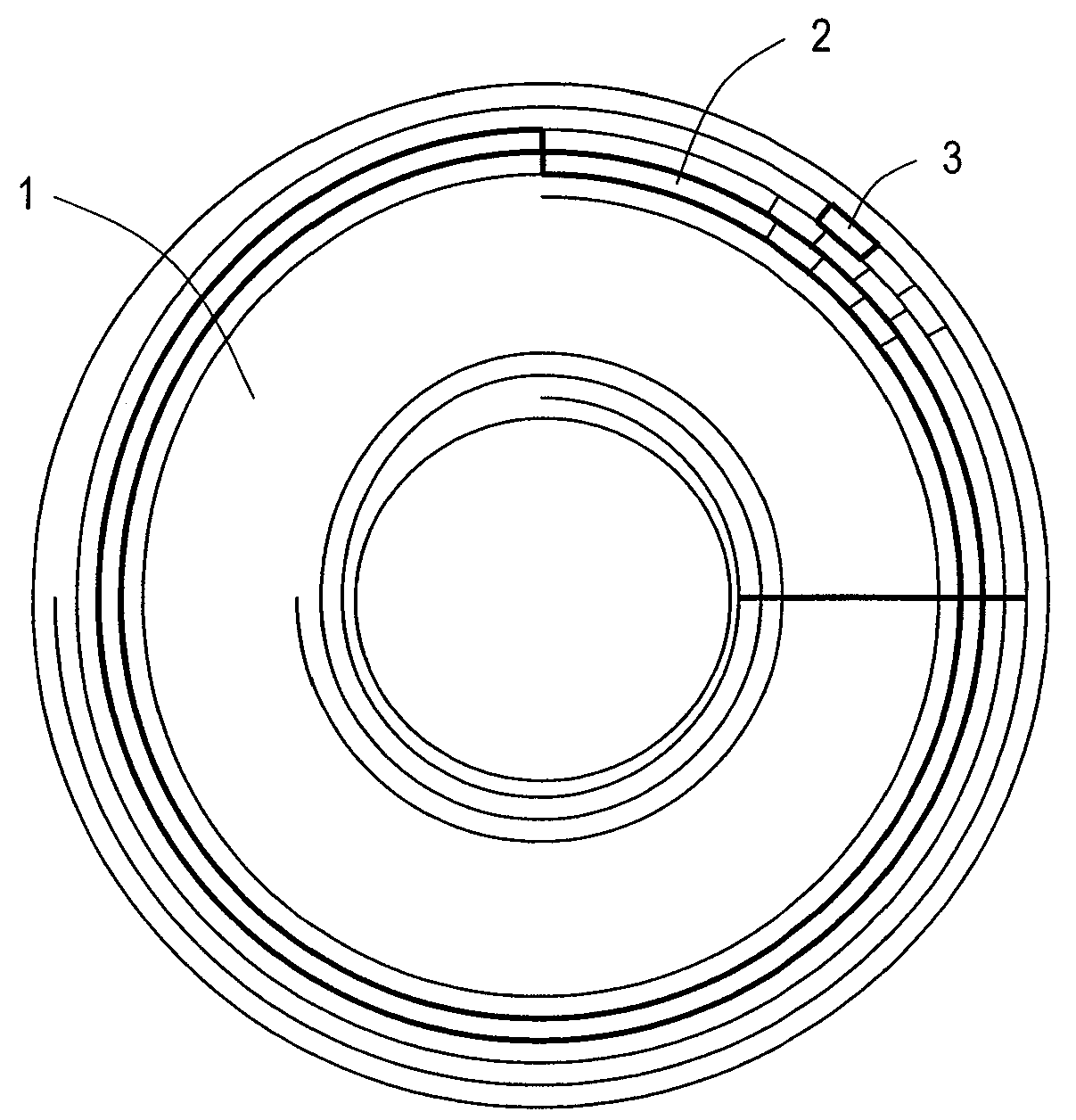
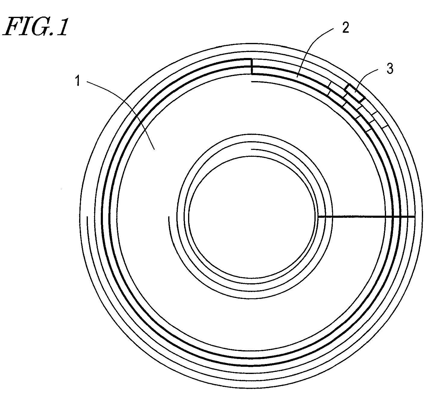
[0099]FIG. 1 shows a physical structure of an optical disc 1 according to this embodiment. On a Discus-Shaped Optical disc 1, a great number of tracks 2 are formed in a spiral, for example. On each track 2, a great number of tiny sectors are formed. As described later, data is recorded on each track 2 in units of blocks 3 having a predetermined size.

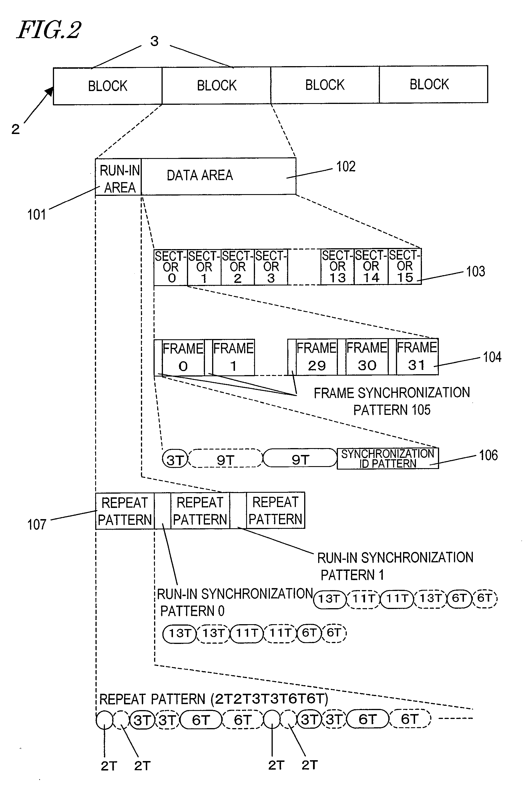
[0100]FIG. 2 shows a recording format of the optical disc 1 according to this embodiment.

[0101]Data is recorded on the track 2 in units of blocks 3 obtained by performing error correction coding processing at every prescribed data amount. The track 2 is assigned block addresses on a block-by-block basis.

[0102]Each block 3 includes a run-in area 101 used for synchronization detection during reproduction provided at the start and a data area 102 including recording data. The data area 102 is divided into a plurality of sectors 103, and each sector 103 is further divided into a plurality of frames 104. At the start of each frame 104, a fram...

embodiment 2

[0115]FIG. 3 is a block diagram showing a structure of an optical disc apparatus 250 according to this embodiment.

[0116]The optical disc apparatus 250 shown in FIG. 3 is capable of both reproducing data from an optical disc 200 and recording data to the optical disc 200. This is merely an example, and the optical disc apparatus 250 only needs to be capable of performing at least one of data reproduction and data recording.

[0117]The optical disc apparatus 250 includes an optical head 201, a motor 202, a servo circuit 203, an address reproducing circuit 204, a CPU 205, a run-in generation circuit 206, a data modulation circuit 207, a recording control circuit 208, a data signal extraction circuit 209, a reproduction clock generation PLL circuit 210, an adaptive equalization circuit 211, a data demodulation circuit 212, and a run-in synchronization detection circuit 213.

[0118]The servo circuit 203, the address reproducing circuit 204, the CPU 205, the run-in generation circuit 206, the...

embodiment 3

[0145]FIG. 6 shows a recording format of an optical disc according to this embodiment. The format shown in this figure is different from the format shown in FIG. 2 in a run-in area 501 included in the block 3. The data area 102 shown in FIG. 6 is the same as the data shown in FIG. 2, and so will not be described. The external structure of the optical disc in this embodiment is the same as the optical disc 1 shown in FIG. 1 according to Embodiment 1.

[0146]In addition, the optical disc according to this embodiment is structured such that the spatial frequency of the shortest bit length 2T is 1.12 times of the OTF cutoff frequency as shown in FIG. 22.

[0147]The run-in area 501 is divided into two areas 507 and 508. The bit pattern in a first area 507 is repeat pattern A shown in FIG. 6, and the bit pattern in a second area 508 is repeat pattern B shown in FIG. 6.

[0148]Pattern A in the first area includes a repetition of 4T / 4T / 5T / 5T. Neither 2T, corresponding to a frequency exceeding the...


PUM


Abstract

A big pattern for a run-in area which allows data reproduction to be performed stably even when the recording density of an optical disc is increased is provided. An optical disc according to the present invention includes tracks, each of which divided into a plurality of recording blocks. Each of the plurality of blocks includes a run-in area and a data area. In the run-in area, a prescribed run-in bit pattern is recordable; and in the data area, bit patterns having a plurality of bit lengths obtained by modulating data as a recording target in accordance with a prescribed modulation rule are recordable. In this optical disc, at least one of spatial frequencies corresponding to the bit patterns having the plurality of bit lengths is higher than a cutoff frequency. The run-in bit pattern recordable in the run-in area includes the bit patterns having the plurality of bit lengths, from which the bit pattern corresponding to the frequency higher than the OTF cutoff frequency has been excluded.

Description

BACKGROUND OF THE INVENTION[0001]1. Field of the Invention[0002]The present invention relates to a recording format usable for recording information on an information recording medium, and a technology for recording or reproducing information in accordance with the recording format.[0003]2. Description of the Related Art[0004]Recently, research and development of high density optical discs has been actively conducted. Currently, for example, Blu-ray Disc (BD) has been proposed and put into practice, and is used for recording digital broadcast or the like. Optical discs are now establishing their position as an important information medium (see “Zukai Blu-ray Disc Dokuhon” (Blu-ray Handbook with Diagrams) published by Ohmsha, Ltd.). For further increasing the density, research and development is being performed for providing a recording density higher than that of the BD to expand the recording capacity.[0005]FIG. 17 shows an example of a conventional recording format. Recording data...

Claims


Application Information

Patent Timeline
IPC IPC(8): G11B7/24
CPCG11B7/005G11B7/0053G11B7/00745G11B20/10222G11B2220/2537G11B20/14G11B2020/1221G11B2020/1287G11B20/1217G11B20/12G11B7/007G11B20/10G11B7/004
Inventor NAKATA, KOHEIMIYASHITA, HARUMITSU
Owner PANASONIC CORP
Why Eureka
Try Eureka