Fibre laser system

a laser system and fibre technology, applied in laser monitoring arrangements, laser optical devices, lasers, etc., can solve the problems of power reflection, large amount, and more difficult with fibre lasers

Active Publication Date: 2009-07-09
SPI LASERS UK
View PDF10 Cites 46 Cited by
  • Summary
  • Abstract
  • Description
  • Claims
  • Application Information

AI Technical Summary

Benefits of technology

[0010]In a first aspect, according to the invention, there is provided a fibre laser system comprising an optical fibre, a part of which is doped with a rare earth to form an optical gain medium; at least one laser diode; means for applying pump radiation from the laser diode to the optical gain medium and for generating a laser beam and delivery fibre means for delivering a laser beam to a workpiece, wherein the fibre laser is provided with at least one means for protecting one or more components from damage caused by errant radiation.
[0014]The fibre may be provided with a means for protecting against errant radiation as described in co-pending Patent Application No 0623452.0. It may comprise a waveguide optically coupled to the at least one diode so as to receive pump radiation, the waveguide having a core, at least a portion thereof being rare-earth doped to provide the gain medium, and also having at least three claddings to confine stray radiation originating in the waveguide system, to guide the radiation, and to cause the radiation to exit the system along a path that avoids impingement upon the at least one diode.
[0017]Preferably, the system may further alternatively comprise one or more power monitors arranged to detect forward propagating power or other characteristics. Preferably, two or more monitors are provided, one monitoring power nearer the beam delivery output end of the system then the other or others to provide a means of measuring power continuity through the delivery fibres. The power detectors are spaced apart so that any standard electronic circuitry will be able to respond in time and switch off the excitation source of the fibre laser before damage is incurred by critical components.

Problems solved by technology

This is more difficult with fibre lasers.
Material processing a highly reflective material such as copper can result in a large amount, perhaps even up to 90% or so, of the power being reflected if the incident pump light is not coupled into the material properly.
This may come as a result of the incident laser beam not having sufficient intensity either through lack of power or the laser output being out of focus.
This reflected power can have serious consequences for the laser source if it is not controlled properly, either through damage of the delivery fibre and surrounding optics or delivery feedback into the source laser causing it to run unstably or causing the light to damage the sensitive pumped diodes.
It will be recalled that pumping radiation from the diodes is applied through a cladding layer to the doped region and therefore any reflected radiation which finds its way back into the cladding layer could, in an unprotected system, find its way directly to the pump diodes where it can severely damage them.
The effect is initiated by a defect in the carrying optical fibre such as damage to an end face or core of the delivery fibre.
This uncontrolled propagation of the optical discharge can propagate into vital components of the fibre laser resulting in its destruction.

Method used


Image

  • Fibre laser system
  • Fibre laser system
  • Fibre laser system

Examples


Embodiment Construction

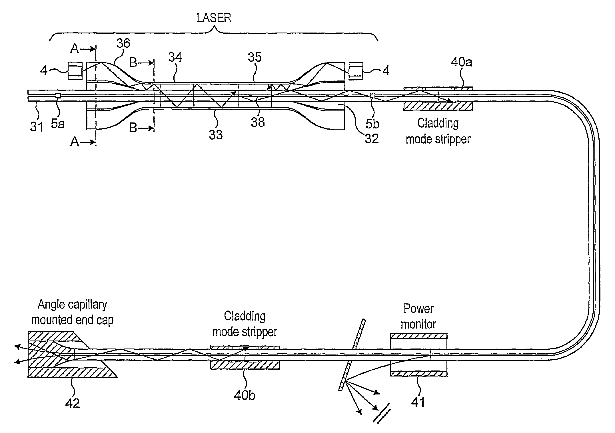
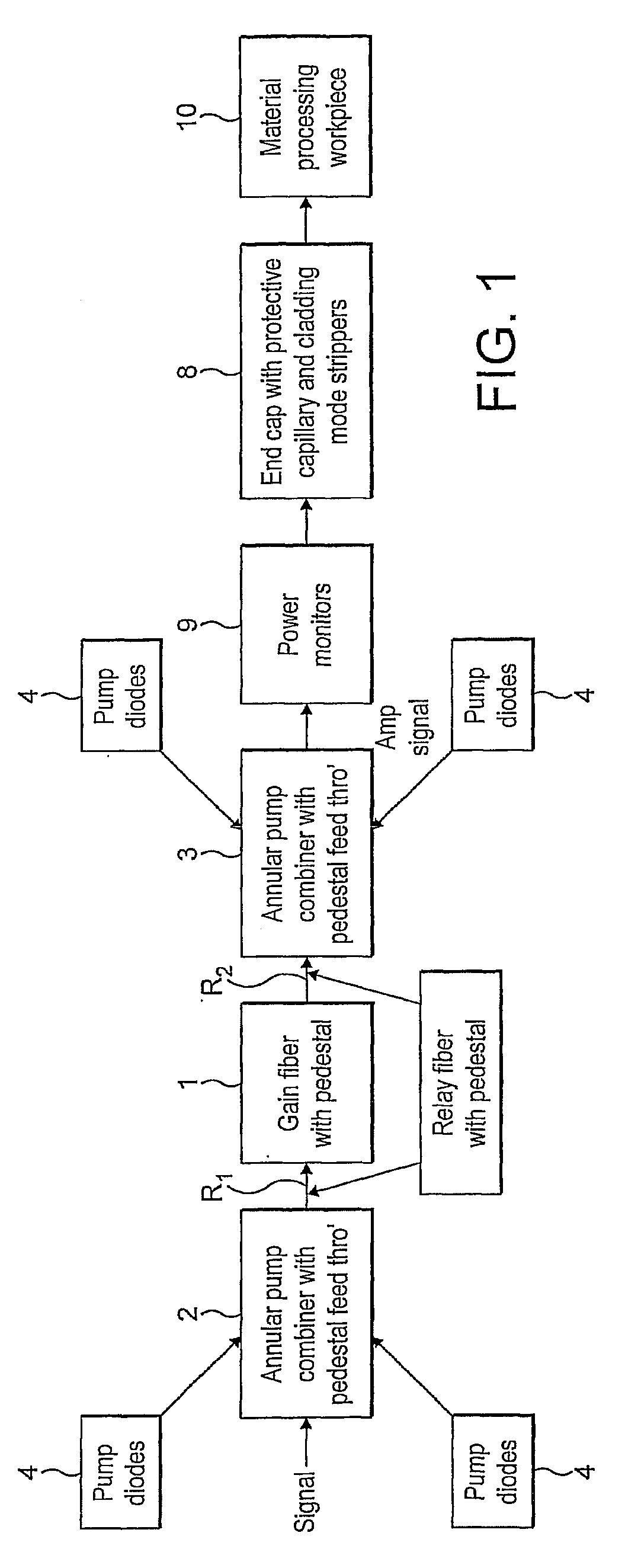
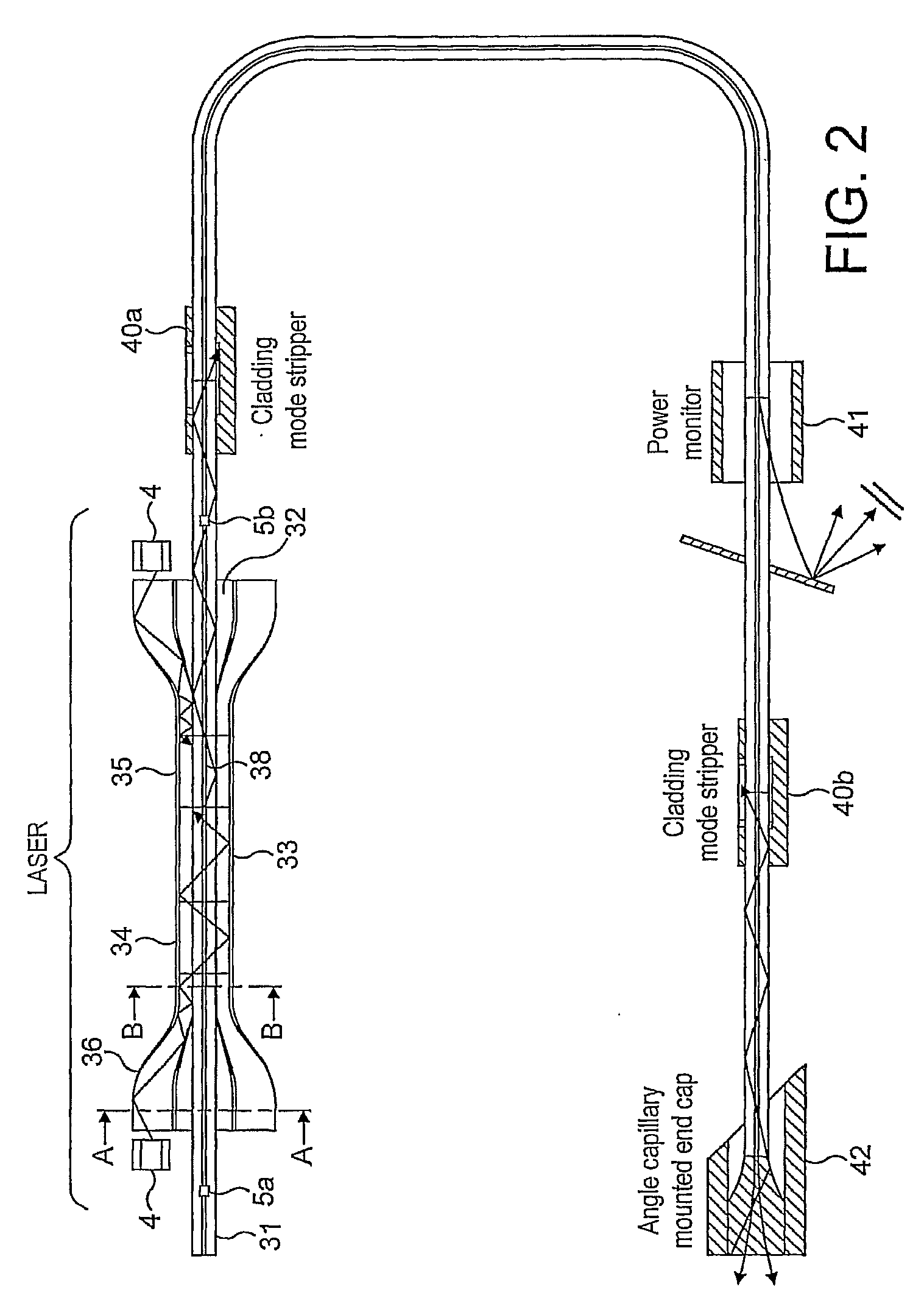
[0045]Referring to FIG. 1, a fibre laser system basically comprises a fibre portion 1 which is doped with a rare earth material to provide an active gain medium; a pump combiner 2, 3 at either end of the gain fibre; semi-conductor laser pumped diodes 4 whose output is applied through the pump combiner into the gain fibre; and relay fibre portions R1, R2 between the gain fibre and the respective pump combiners 2 and 3. The number of pump diodes may be chosen according to the nature of the laser and the particular application, there may be any number from one upwards. The gain fibre can be used in an amplifier configuration or as a laser by appropriate feedback. The laser energy is output over a delivery fibre 7 to a termination having an end cap with protective capillary and also one or more cladding mode strippers 8. One or more power monitoring stations 9 are used to monitor the power in the delivery fibre and to provide fault indications. The laser beam is launched from the end of...


PUM

PropertyMeasurementUnit
angleaaaaaaaaaa
angleaaaaaaaaaa
angleaaaaaaaaaa

Abstract

A fibre laser system is disclosed comprising an optical fibre, a part of which is doped with a rare earth to form an optical gain medium; at least one laser diode; means for applying pump radiation from the laser diode to the optical gain medium and for generating a laser beam and delivery fibre means for delivering a laser beam to a workpiece, wherein the fibre laser is provided with at least one means for protecting one or more components from damage caused by errant radiation. Several different means of protection are disclosed.

Description

[0001]This invention relates to a fibre laser system.[0002]In particular, it relates to a fibre laser system having high damage resistance and which is immune or substantially immune from feedback from a material processing operation. The material processing operation may be cutting, welding or any other processing operation.BACKGROUND OF THE INVENTION[0003]Cladding pumped fibre lasers are becoming more common. In these types of lasers, a core of an optical fibre is doped with a rare earth element to become an active gain medium and pump radiation is applied via a cladding layer. The pump radiation is normally produced by semi-conductor laser diodes and a means is provided for coupling their input into the cladding of the rare earth doped fibre. Bragg gratings formed in the core of the optical fibre are employed as mirrors to form a laser cavity.[0004]Co-pending UK Patent Applications Nos 0612463.0 and 0623452.0 describe schemes for coupling pump radiation into or out of an optical ...

Claims


Application Information

Patent Timeline
Patent Type & Authority Applications(United States)
IPC IPC(8): H01S3/30
CPCB23K26/0639B23K26/422G02B6/2835H01S3/0014H01S3/005B23K26/0626H01S3/06729H01S3/06745H01S3/094003H01S3/094007H01S3/0064B23K26/064B23K26/702
Inventor LI, CHENGBOTHEROYD, IAINLEWIS, STEFFANEDWARDS, GLYNKEEN, STEPHEN
Owner SPI LASERS UK
Why Eureka
Try Eureka