Cam followers for long life

a cam follower and long-life technology, applied in the direction of bearings, shafts and bearings, rotary bearings, etc., can solve the problems of tensile pushed cam followers, lubrication failure, corrosion, etc., to reduce the incidence of spalling or at least substantially reduce the incidence of spalling, prevent or reduce the fatiguing of metal

a cam follower and long-life technology, applied in the direction of bearings, shafts and bearings, rotary bearings, etc., can solve the problems of tensile pushed cam followers, lubrication failure, corrosion, etc., to reduce the incidence of spalling or at least substantially reduce the incidence of spalling, prevent or reduce the fatiguing of metal

US20090175567A1Inactive Publication Date: 2009-07-09ROLLER BEARING OF AMERICA

Image

  • Cam followers for long life
  • Cam followers for long life
  • Cam followers for long life

Examples


Embodiment Construction

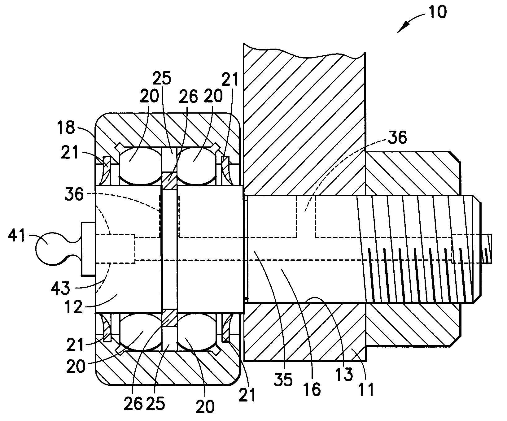
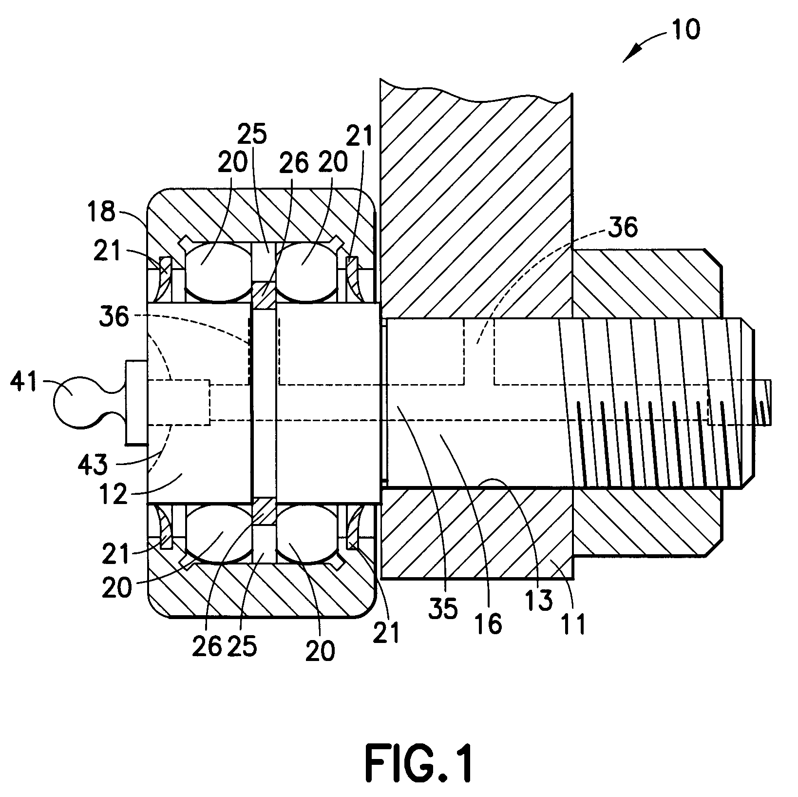
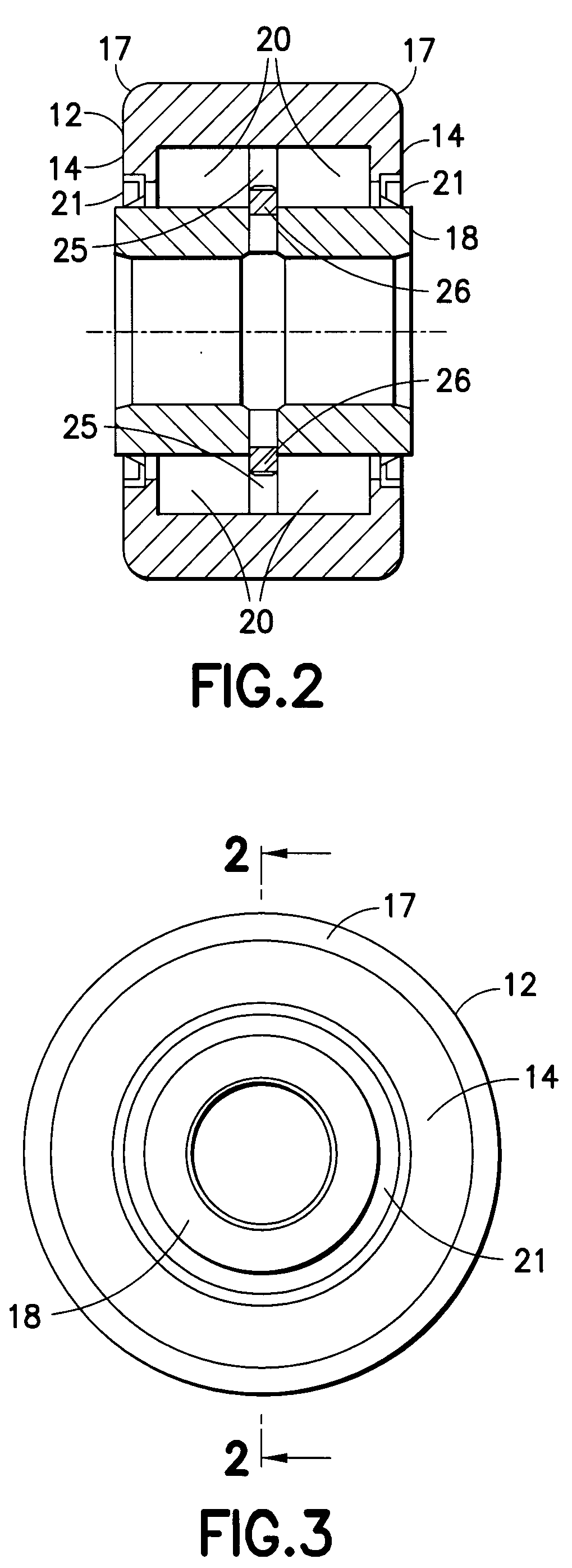
[0016]As is shown with reference to FIG. 1, a cam follower assembly is designated generally by the reference numeral 10 and is hereinafter referred to as “assembly 10.” Assembly 10 comprises an inner race 12 located axially in an outer race 18. Rollers 20 are positioned between the inner race 12 and the outer race 18 such that the inner race and the outer race can rotate relative to each other. A split ring 26 is positioned in a space 25 between the rollers 20. Seals 21 are located in the outer race 18 and provide wiping communication with the inner race 12.

[0017]The assembly is carried by a shaft 16, which is mounted in a bore 13 in a carrier member 11. The shaft 16 is shown as being threaded; however, the present invention is not limited in this regard, as the shaft may be press-fit into the carrier member 11 or retained therein by any other suitable method.

[0018]A lubrication fitting 41 may be located on one or both ends of the shaft 16 to allow for the introduction of lubricant ...


PUM


Abstract

A cam follower assembly has an outer race and an inner race located therein. Rollers are located between the outer and inner races to enable the two races to rotate relative to one another. The surfaces of the inner race are lapped and subsequently treated using a cold plastic deformation process. This process is a dry mechanical process that involves applying a high energy flow of abrasive material in a carrier medium to the metal surfaces of the inner race. The present invention is not limited to treatment of the surfaces of the inner race, however, as the surfaces of the outer race as well as the surfaces of the rollers may be similarly treated.

Description

CROSS-REFERENCE TO RELATED APPLICATION[0001]This application claims the benefit of U.S. Provisional Application No. 61 / 019,956 filed Jan. 9, 2008, which is incorporated herein by reference.FIELD OF THE INVENTION[0002]This invention relates to roller bearings and, more particularly, to roller bearings for use as cam followers which have an increased life.BACKGROUND OF THE INVENTION[0003]A roller bearing typically comprises rollers that are held between an inner race and an outer race. The rollers are cylindrically-shaped elements that facilitate the rolling engagement of the inner race relative to the outer race. Plain roller bearings include rollers that are right circular cylinders and are mounted in races in which the outer surfaces thereof are parallel to the axis of rotation of the rollers. When the rollers are very long and thin (as compared to other rollers), the rollers are typically referred to as “needle bearings.” When the rollers are conical in shape and run on races havi...

Claims


Application Information

Patent Timeline
09 Jul 2009
Publication
US20090175567A1
IPC
F16C19/28
CPC
F16C19/28; F16C13/006
Inventors
PRESCAVAGE, JAMES; LUGOSI, ROBERT