Thermally conductive structure

a technology of thermal conductivity and structure, applied in the field of thermal conductivity structures, can solve the problems of high price, poor choice of materials for designers, deformation, stretching, tearing, etc., and achieve the effect of reducing the thermal deformation of the first surfa

Active Publication Date: 2009-07-16
STRAZA GEORGE C P
View PDF12 Cites 23 Cited by
  • Summary
  • Abstract
  • Description
  • Claims
  • Application Information

AI Technical Summary

Benefits of technology

[0011]In a fifth aspect of the invention, a method for utilizing a thermally conductive chevron is disclosed. In one embodiment, the method comprises: providing the thermally conductive chevron, wherein the thermally conductive chevron comprises a plurality of hexagonal cells formed from a plurality of cell walls; a first surface perpendicular to the hexagonal cells and bonded to a firs

Problems solved by technology

Without an adequate transfer mechanism for the heat, the resulting differential thermal expansion can cause stretching, tearing, and/or deformation in the structure or supporting materials.
While the structure may b

Method used


Image

  • Thermally conductive structure
  • Thermally conductive structure
  • Thermally conductive structure

Examples


Embodiment Construction

[0033]In the following description of exemplary embodiments, reference is made to the accompanying drawings which form a part hereof, and in which it is shown by way of illustration specific embodiments in which the invention may be practiced. It is to be understood that other embodiments may be utilized and structural changes may be made without departing from the scope of the present invention.

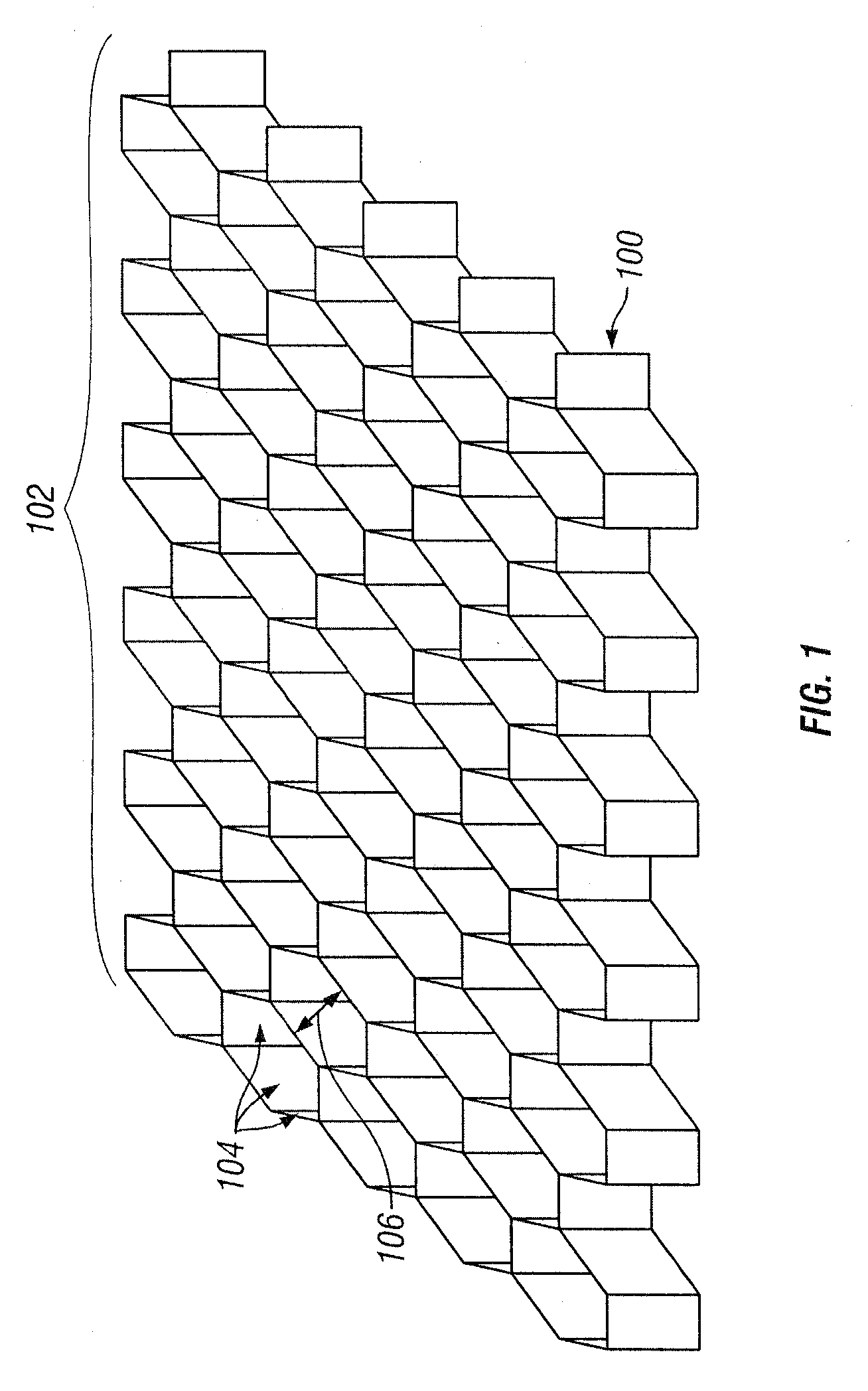
[0034]Although embodiments of the invention may be described and illustrated using a core layer comprising a honeycomb structure, it should be understood that embodiments of this invention are not so limited, but may also include other structural configurations, shapes, and / or cellular geometries.

[0035]FIG. 1 is an illustration of a section of a honeycomb structure 100 that may be used according to one embodiment of the invention. The hexagonal cells of the honeycomb structure 100 allow a structure to resist bending. In this example, the honeycomb structure 100 comprises a plurality of hexag...


PUM

PropertyMeasurementUnit
Thicknessaaaaaaaaaa
Structureaaaaaaaaaa
Electrical conductoraaaaaaaaaa

Abstract

A multi-layered honeycomb structure adapted to reduce and/or eliminate thermal deformation is disclosed herein. In some embodiments, walls of the honeycomb structure comprise a first layer, optionally, a second layer, and a core layer adjacent to the first layer or between the first and second layers. The first and second layers may be compositions of Inconel or other high strength materials. The core layer may be copper or another thermally conductive material. The core layer is adapted to transmit heat between a first region of a structure and a second region. In this manner, heat can be transferred from the heated region to an unheated region, thereby reducing the temperature difference between the regions and thus the amount of thermal deformation.

Description

CROSS-REFERENCE TO RELATED APPLICATIONS[0001]This application claims priority to U.S. Provisional Patent Application Ser. No. 61 / 020,688, filed on Jan. 11, 2008, the contents of which are incorporated by reference herein.FIELD OF THE INVENTION[0002]The present invention relates generally to the field of thermally conductive structures. More particularly, the present invention is directed in one exemplary aspect to providing a thermally conductive structure adapted to reduce thermal deformation.BACKGROUND OF THE INVENTION[0003]Many structural components of buildings, vehicles, mechanical devices and other works of construction include regions which are normally subjected to higher temperatures than other regions. For example, in a jet engine of an aircraft, the inner region of the engine housing (i.e., the surface of the engine housing closer to the exhaust) typically reaches higher temperatures than the outer region. The differences in temperature are often related to the thermal co...

Claims


Application Information

Patent Timeline
IPC IPC(8): F02C7/24B32B3/12B29C70/68B32B7/027
CPCB29D99/0089Y10T428/24149C22C1/002C22C9/00C22C19/055F02K1/822Y02T50/671F05D2250/11F05D2250/132F05D2300/5021F05D2300/5024Y02T50/675B32B7/02B32B7/045B32B7/12B32B15/043B32B15/18B32B15/20B32B3/14B32B3/18B32B3/28B32B2250/03B32B2250/40B32B2307/302B32B2307/308B32B2307/54B32B2307/552B32B2307/714B32B2307/734B32B2605/00B32B2605/18Y10T156/1003B32B3/12F01D11/127B32B7/05Y02T50/60B32B7/027C22C1/11
Inventor STRAZA, GEORGE C. P.
Owner STRAZA GEORGE C P
Why Eureka
Try Eureka