Method for extinguishing a smouldering fire in a silo

a technology of silo and fire, applied in the field of silo extinguishing fire, can solve the problems of increasing the risk of biogas, reducing the amount of oxygen needed for an open fire, and reducing the risk of explosion

a technology of silo and fire, applied in the field of silo extinguishing fire, can solve the problems of increasing the risk of biogas, reducing the amount of oxygen needed for an open fire, and reducing the risk of explosion

US20090178814A1Inactive Publication Date: 2009-07-16LINDE AG

Image

  • Method for extinguishing a smouldering fire in a silo
  • Method for extinguishing a smouldering fire in a silo
  • Method for extinguishing a smouldering fire in a silo

Examples


Embodiment Construction

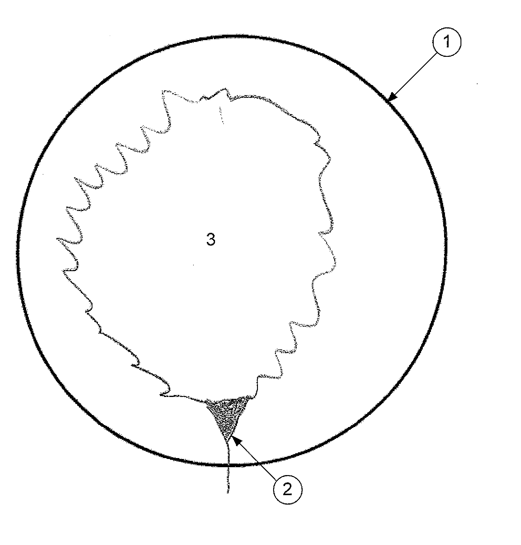
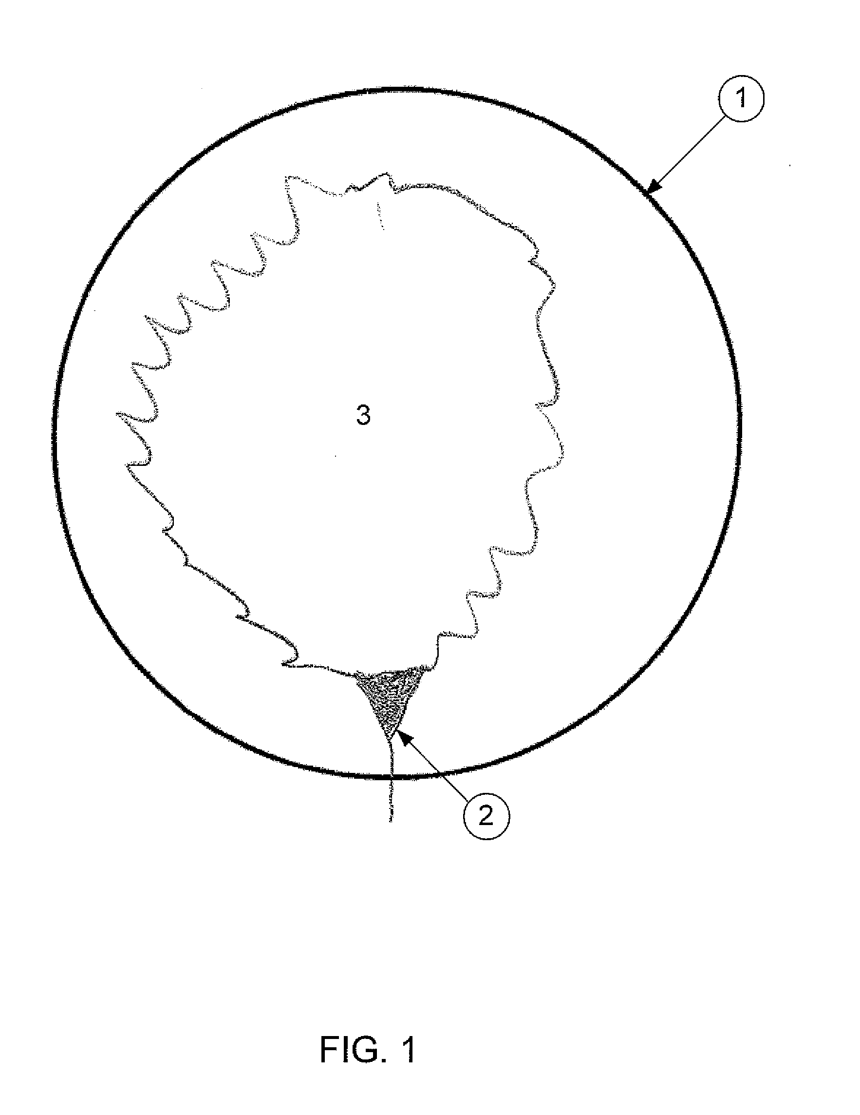
[0037]FIG. 1 shows an inert gas layer 3 formed by one venturi-type nozzle 2 in a silo 1 with a small diameter, e.g., with a diameter less than 3 m. The inert gas is injected as liquid gas through one venturi-type nozzle 2 above the stored content in the silo with a slow streaming velocity in such a way that mass ration of the entrained surrounding gas to the incoming liquid inert gas is between 0.5 and 20, preferably in the range 1.0 and 5.0. The venturi-type nozzle 2 is essentially horizontal oriented. Thereby an essentially horizontal flat inert gas layer 3 is formed above the smouldering fire.

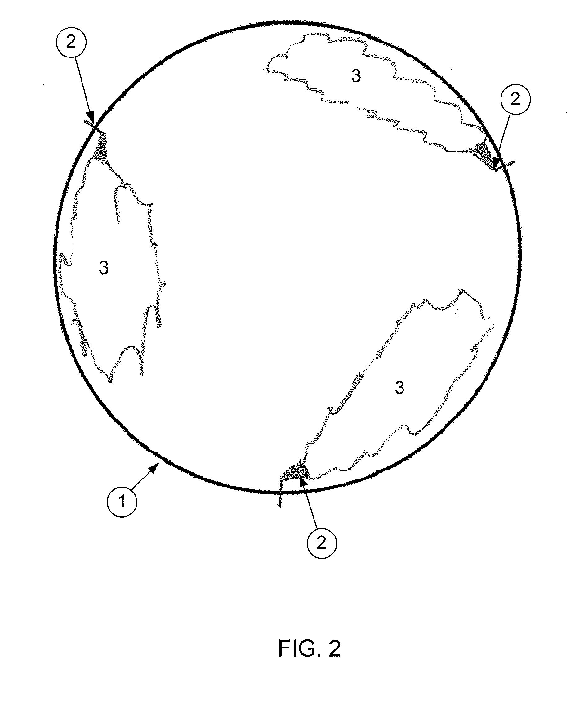
[0038]FIG. 2 shows one embodiment of the invention in a silo 1 with a larger diameter, e.g., more than 3 m. The inert gas is injected through three venturi-type nozzle 2 oriented in acute angle form the silo wall. Thereby no overlap of the resulting inert gas clouds 3 occurs. The formation of turbulence and air mixing into the inert gas layer is avoided and thereby a closed inert gas layer i...


PUM


Abstract

The invention relates to a method for extinguishing a smouldering fire in a silo by introducing inert gas into the silo. The inert gas is introduced through a venturi-type nozzle above the stored content in the silo with a slow streaming velocity in such a way that mass ratio of the entrained surrounding gas to the incoming liquid inert gas is between 0.5 and 20. Thus a closed inert gas layer is formed above the smouldering fire.

Description

BACKGROUND OF THE INVENTION[0001]The invention relates to a method for extinguishing a smouldering fire in a silo by introducing inert gas into the silo. The invention further relates to a silo for storing deposited goods having at least one inlet for inert gas.[0002]It is not uncommon for silos with biomass to have fires and in particular smouldering fires. Biomass always contains highly combustible components. In addition, the fermentation of biomass produces heat and biogas. The heat itself may be sufficient to start a fire. Biogas makes matters even more dangerous since it substantially comprises carbon dioxide, water and the highly combustible gas methane. Said biogas has a high heating value. A different source of ignition may be materials which collect electric charge for instance synthetic materials are charged electrostatically by friction and may ignite the biogas through electric discharge and thus form the starting point of a fire in the stored material.[0003]The void sp...

Claims


Application Information

Patent Timeline
16 Jul 2009
Publication
US20090178814A1
IPC
A62C3/04; A62C31/02; E04H7/22
CPC
A62C3/04
Inventors
HEISEL, MICHAEL; LEE, RON CLARK