Dual ring dedicated drive control system for medium voltage variable frequency drives

Inactive Publication Date: 2009-07-16
ROCKWELL AUTOMATION TECH
View PDF11 Cites 2 Cited by
  • Summary
  • Abstract
  • Description
  • Claims
  • Application Information

AI Technical Summary

Benefits of technology

[0008]The present invention provides a motor drive system that is substantially more resistant to failure. Generally the motor drive system provides a redundant communication topology with the drives, greatly reducing the chance of failure caused by a fault in the drive-to-drive communication link. Further, the invention designates one of the drives as a “Link Keeper” that can reconfigure the drive-to-drive communication link without intervention of the PLC. This provides integrity of the drive system even in the absence of communication with the PLC or failure of the PLC (1 and 2 above) and substantially reduces failure of the drive-to-drive communication link (3 above). The system readily adapts to optical fiber allowing extremely high-speed communication with low latency.

Problems solved by technology

The main disadvantage experienced by such existing systems, is the creation of network latencies, that is, delays caused by network propagation delays and processing times in the system controllers and MV Drives.
In critical applications, such as conveyors, such communication latency can create undesirable lateral or torsional vibrations.
Another disadvantage of existing systems is that each MV Drive operates asynchronously from each other such that regulators add to the vibration in conveyor systems.
However, such secondary links are typically over copper wire and therefore suffers from some of the same limitations as the industrial network such as lack of fault tolerance, excess latencies, limitations on distances, and the limitations of available bandwidth.
Thus the motor drive system, even with a secondary drive-to-drive communication link, is susceptible to failure of (1) the PLC, (2) the main industrial control network, (3) the drive-to-drive communication link, and (4) the drive designated as the controlling drive.

Method used


Image

  • Dual ring dedicated drive control system for medium voltage variable frequency drives
  • Dual ring dedicated drive control system for medium voltage variable frequency drives
  • Dual ring dedicated drive control system for medium voltage variable frequency drives

Examples


Embodiment Construction

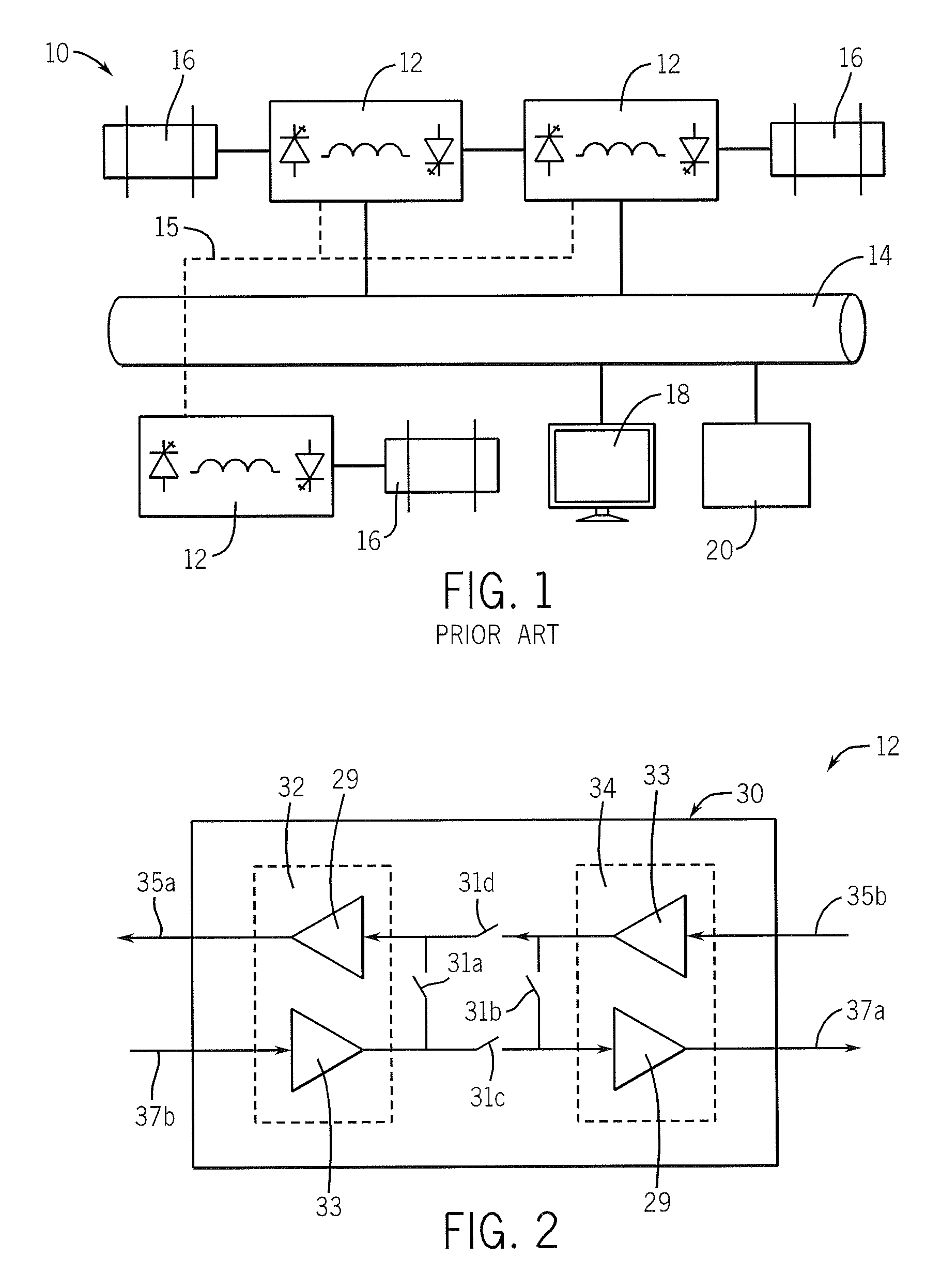
[0030]Turning now to the drawings and initially FIG. 1, a schematic illustration of a multiple drive system 10 of the type known in the prior art includes a plurality of drives 12 coupled to an industrial control network 14 such as, for example, ControlNet. Each drive 12 is in communication with a motor 16. In such systems 10, one of the drives 12 is typically designated as the main controlling drive while the remaining drives are designated as followers. In such applications, typically the main controlling drive is responsible for the control of the speed while the followers are configured to assist in providing torque to the motors 16 of the system.

[0031]Motion control data is transferred between the drives 12 by way of a dedicated drive-to-drive communication network 15, while configuration data for the drives 12 and for their communication on drive-to-drive communication network 15 is communicated over the industrial control network 14. The network 14 may be shared with other co...


PUM


Abstract

The present invention provides a motor drive system that is substantially more robust than those of the prior art. Generally, the motor drive system provides a redundant communication topology with the drives, thereby greatly reducing the chance of failure by a fault in the drive-to-drive communication link. Specifically, the motor drive system includes a plurality of motor drives joined by a communication media. Each motor drive has a motor control circuit configured to control the speed of an electric motor and a media access control unit having two communication modules. Each communications module includes a transmitter and a receiver joined to the communications media. A set of routing switches in the media access control unit joins the communication modules to connect the motor drives in an independent primary and a secondary ring communicating data for controlling the motor drives.

Description

STATEMENT REGARDING FEDERALLY SPONSORED RESEARCH OR DEVELOPMENT[0001]N / ACROSS REFERENCE TO RELATED APPLICATION[0002]N / ABACKGROUND OF THE INVENTION[0003]The present invention relates generally to a control system for medium voltage variable frequency drives, and specifically to a control system for connecting multiple variable frequency drives together with a fiber optic communication ring.[0004]In applications requiring multiple medium voltage variable frequency drives (“MV Drives”), there is typically a single drive designated as the main controlling drive. The remaining drives are then designated as followers. In such applications, typically the main controlling drive is responsible for the control of the overall speed (i.e., speed regulator), while the followers are responsible for assisting in providing the torque (i.e., torque regulators) to the motors in the system. In this arrangement, data is transferred from drive to drive over an industrial network such as, for example, De...

Claims


Application Information

Patent Timeline
IPC IPC(8): H02P5/00
CPCH04L12/437G05B19/4185Y02P90/02
Inventor WORRALL, STEPHEN J.
Owner ROCKWELL AUTOMATION TECH
Why Eureka
Try Eureka