

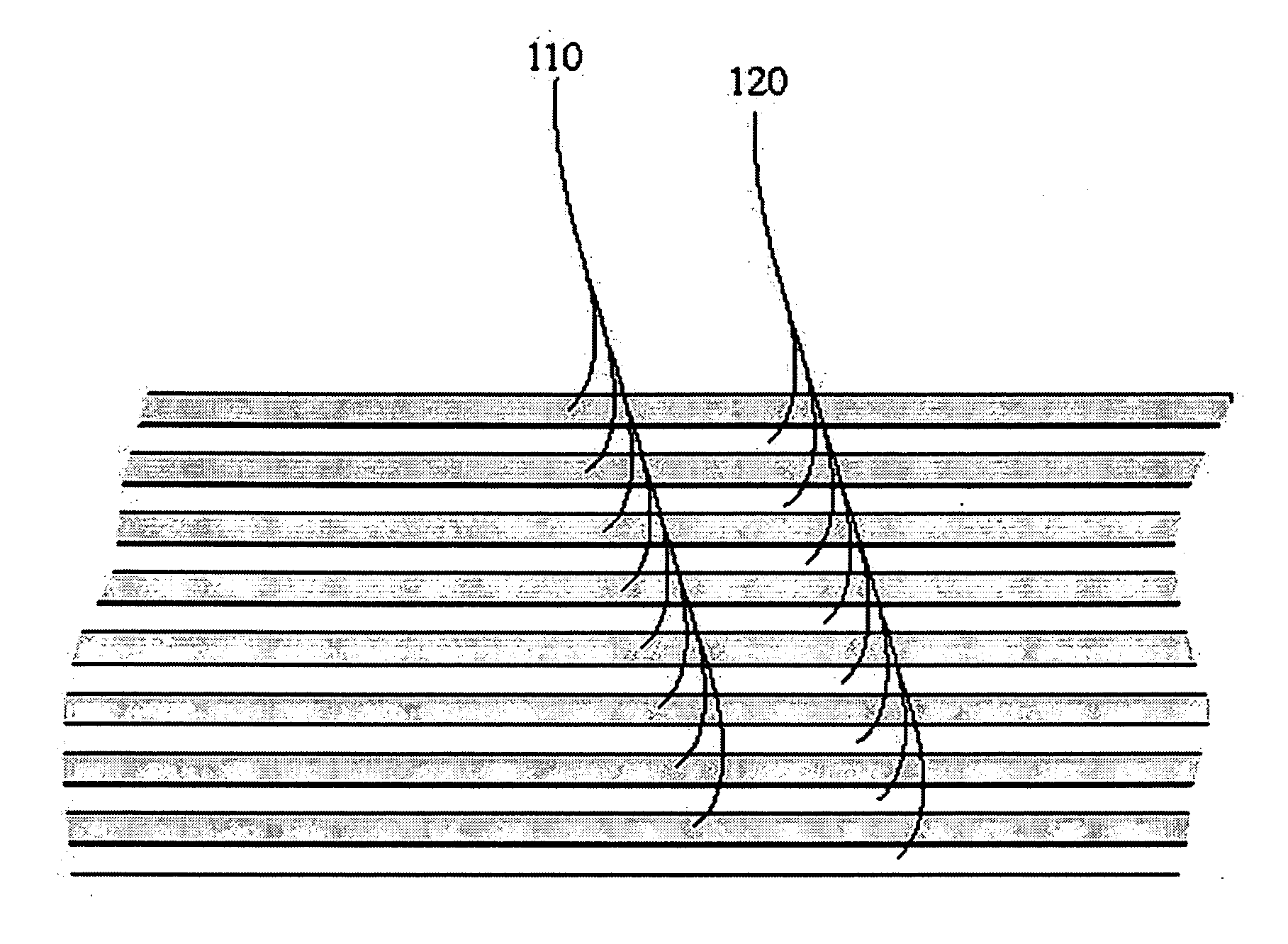
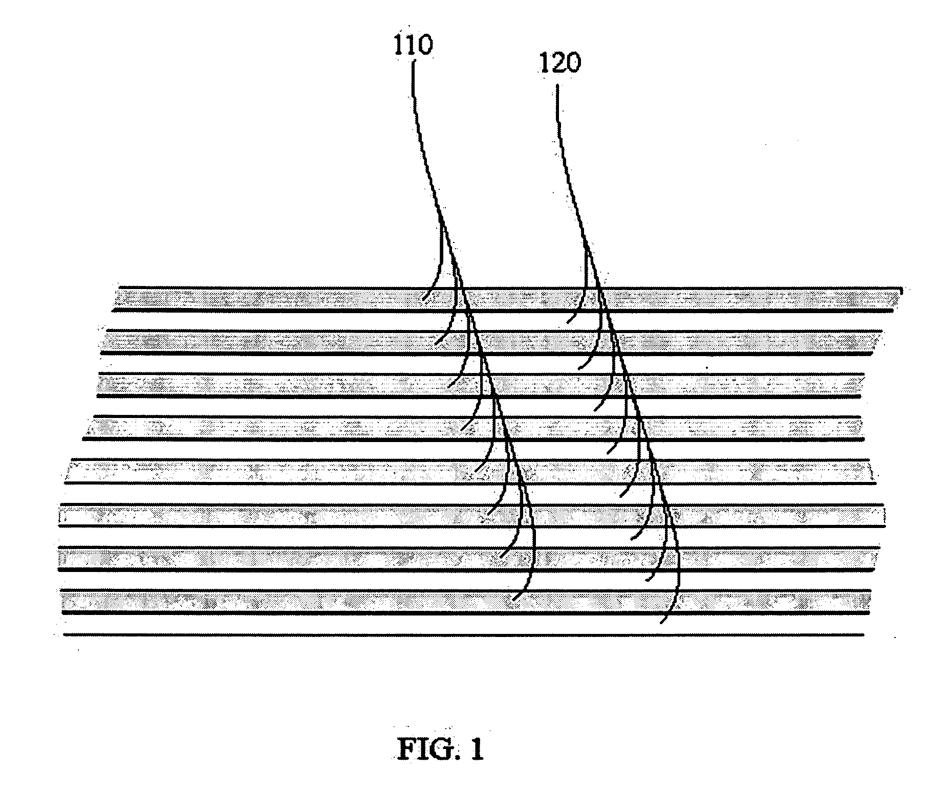
Thin Film Encapsulation for Thin Film Batteries and Other Devices
- Summary
- Abstract
- Description
- Claims
- Application Information
AI Technical Summary
Benefits of technology
Problems solved by technology
Method used
Image

Examples
examples of embodiments
Example 1
[0020]Some embodiments use the encapsulation method described to protect a lithium anode from moisture and air. These embodiments comprise a 1 in2 metal foil substrate measuring approximately 50 μm in thickness. A 0.5 μm thick conductive barrier layer is disposed on at least one surface of the substrate using one of the methods generally available to one ordinarily skilled in the art in addition to those described here. A 3.5 μm thick LiCoO2 positive cathode is disposed onto the conductive barrier layer. A 1.2 μm thick Lipon electrolyte layer is disposed onto the cathode layer and a 9 μm thick Li anode is disposed onto the electrolyte. A 3 μm thick thin-film multilayer encapsulation, consisting of 15 sub-layers of 0.1 μm Zr alternated with 15 sub-layers of 0.1 μm of ZrN, is then disposed on the layered device. This specific embodiment can achieve 500 h in 85° C. / 85% RH environment.
example 2
[0021]Other embodiments may combine five of the encapsulated battery cells discussed previously. This embodiment generally has a total thickness less than 0.5 mm and supplies 2.5 mAh at ½ C rate at 25° C. between 4.2-2.0V.
example 3
[0022]Yet other embodiments of the present invention comprise a 0.5 μm conductive barrier layer, a LiCoO2 positive cathode with a thickness of about 12 μm, a 1.2 μm Lipon electrolyte layer, a Li anode with a thickness of about 10 μm, and a 2 μm thick Lipon modulator layer on top of the Li anode. These embodiments may be fabricated on a 50 μm metal foil substrate of 1 in2 in area and encapsulated by a 3 μm thin-film encapsulation. This embodiment has a total thickness of less than 80 μm and generally supplies 2 mAh at ½ C rate at 25° C. between 4.2-2.0V.
PUM
 Abstract
Description
Claims
Application Information