Activating matrix for cathodic protection

a technology of activating matrix and cathodic protection, which is applied in the field of galvanic cathodic protection of steel, can solve the problems of cracking and delamination, destroying the ability of concrete to keep the steel in a passive, non-corrosive state, and contaminated concrete, and achieves the effect of improving the performance and service life of embedded anodes

Inactive Publication Date: 2009-07-23
BENNETT JOHN E
View PDF9 Cites 3 Cited by
  • Summary
  • Abstract
  • Description
  • Claims
  • Application Information

AI Technical Summary

Benefits of technology

[0022]The present invention also relates to a method of cathodic protection of reinforced concrete, and more particularly, to a method of improving the performance and service life of embedded anodes intended to apply cathodic protection to reinforcing steel and other metals embedded in concrete.

Problems solved by technology

Unfortunately, since concrete is inherently somewhat porous, exposure to salt over a number of years results in the concrete becoming contaminated with chloride ions.
When the chloride reaches the level of the reinforcing steel, and exceeds a certain threshold level for contamination, it destroys the ability of the concrete to keep the steel in a passive, non-corrosive state.
When this tensile force exceeds the tensile strength of the concrete, cracking and delaminations develop.
With continued corrosion, freezing and thawing, and traffic pounding, the utility or integrity of the structure is finally compromised and repair or replacement becomes necessary.
Reinforced concrete structures continue to deteriorate at an alarming rate.
Structurally deficient bridges are those that are closed, restricted to light vehicles only, or that require immediate rehabilitation to remain open.
The damage on most of these bridges is caused by corrosion.
Of these techniques, only cathodic protection is capable of controlling corrosion of reinforcing steel over an extended period of time without complete removal of the salt-contaminated concrete.
This results in cathodic polarization of the steel, which tends to suppress oxidation reactions (such as corrosion) in favor of reduction reactions (such as oxygen reduction).
This type of cathodic protection has been generally successful, but problems have been reported with reliability and maintenance of the power supply.
Problems have also been reported related to the durability of the anode itself, as well as the concrete immediately adjacent to the anode, since one of the products of reaction at an inert anode is acid (H+).
Acid attacks the integrity of the cement paste phase within concrete.
Finally, the complexity of ICCP systems requires additional monitoring and maintenance, which results in additional operating costs.
These techniques are all relatively complex and difficult to perform.
But some embodiments, such as the use of high pH to maintain the anode in an electrochemically active state as described by Page, result in protective current that is small and often inadequate to mitigate corrosion.
Use of the chemicals disclosed by Bennett, such as lithium nitrate and lithium bromide, result in a higher current, but even this current is sometimes inadequate in cases of high chloride contamination and the presence of strong corrosion of the reinforcing steel.

Method used


Image

  • Activating matrix for cathodic protection

Examples


example 1

[0033]A steel reinforced 12×12×4-inch (30.5×30.5×10.2 cm) concrete test block was constructed using concrete with the following mix proportions:

Type 1A Portland cement - 715 lb / yd3Lake sand fine aggregate -1010 lb / yd3No. 8 Marblehead limestone -1830 lb / yd3Water - 285 lb / yd3Chloride (added as NaCl) -  5 lb / yd3Airmix air entrainer (0.95% oz / CWT) -about 6.5% air

[0034]The test block contained about 24 inches (60 cm) of #4 (12 mm dia.) reinforcing bar, or about 0.25 square feet (240 square centimeters) of steel surface area Each test block was cast with two blockouts for two test cells, each blockout forming a circular test cavity about 4 inches (10 cm) in diameter ×2.75 inches (7 cm) deep.

[0035]An anode was first constructed by soldering 40 grams of pure zinc to galvanized tie wires. The zinc was then cast into a mixture containing 65% sand, 15.2% Type III cement, and 19.8% lithium liquid mixture, prepared by combining 40% by volume saturated lithium bromide solution and 60% by volume s...

example 2

[0038]A steel reinforced test block was constructed as in Example 1 above, and a control anode was also prepared as described in Example 1.

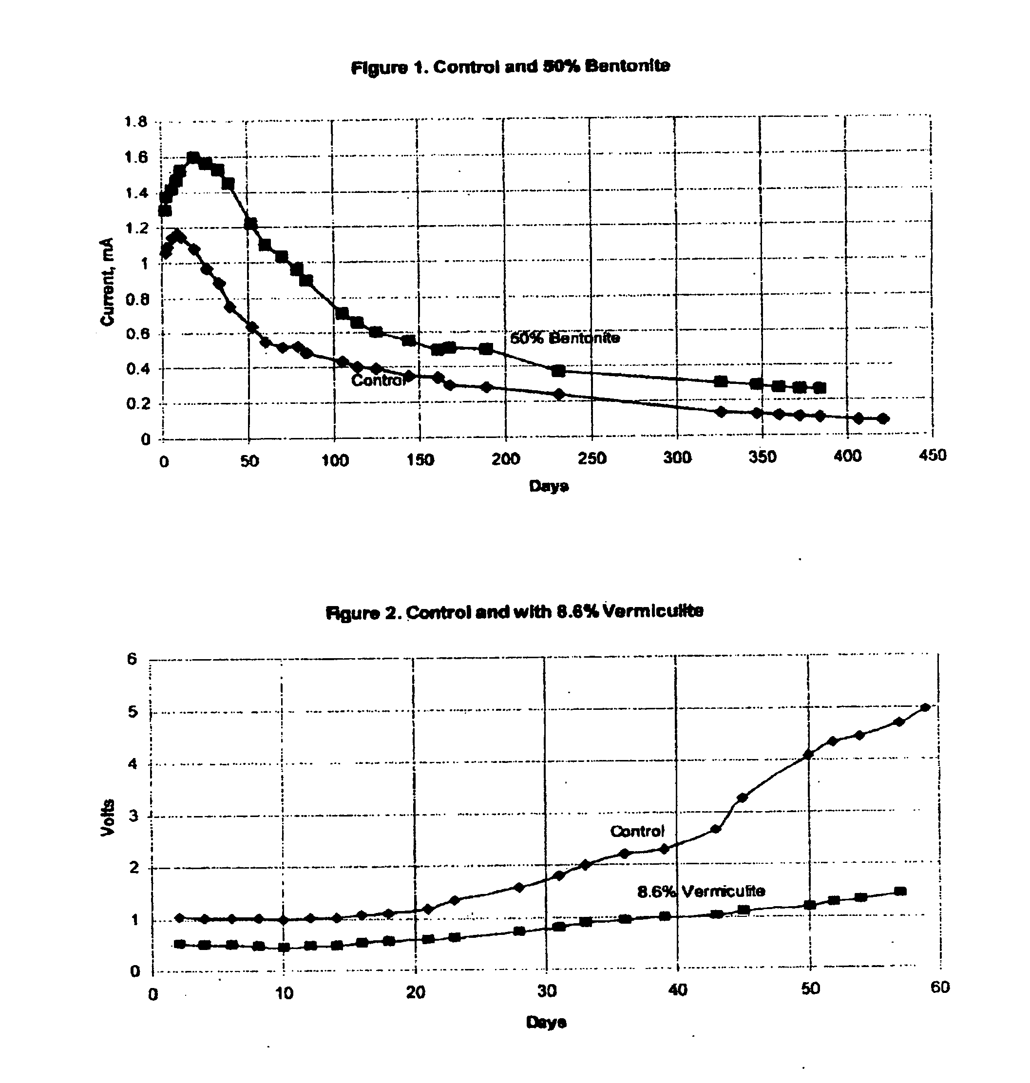
[0039]This anode was subjected to 5 mA of impressed current in constant current mode of operation. In this way, a total charge equivalent to several years of service life can be impressed on the anode in a period of about 60 days. The effectiveness of the anode can be determined by observation of the cell operating voltage. Lower operating voltage indicates that an anode will deliver a higher level of protective current when operated in galvanic mode.

[0040]The operating voltage of the control anode is shown by the line labeled “Control” on FIG. 2. Operating voltage began at about 1.0 volt, and increased to about 5.0 volts after 60 days.

[0041]A second anode was prepared in a similar manner, except that the matrix surrounding the anode contained 8.6% vermiculite by weight. After curing of the mortar surrounding the anode, the anode was placed into ...


PUM

PropertyMeasurementUnit
diameteraaaaaaaaaa
diameteraaaaaaaaaa
surface areaaaaaaaaaaa

Abstract

The galvanic cathodic protection of reinforced concrete structures such as bridges, buildings, parking structures, piers, and wharves, is enhanced by the use of an inert water absorbent solid. The absorbent solid and chemicals are mixed with a cementitious binder to form an activating matrix. This matrix surrounds a sacrificial metal anode such as zinc, or aluminum or their alloys. The metal anode is electrically connected to the ferrous reinforcing member by a metallic conductor. The water absorbent solid may be a clay such as bentonite or a hydrated mineral such as vermiculite. It is preferably in the form of discrete particles dispersed throughout the binder. The inclusion of the absorbent solid in the activating matrix serves to increase the protective current, thereby reducing corrosion of the reinforcing components of the concrete structure.

Description

BACKGROUND OF THE INVENTION[0001]1. Technical Field[0002]This invention generally relates to the field of galvanic cathodic protection of steel embedded in concrete structures, and is particularly concerned with the performance of embedded sacrificial anodes, such as zinc, aluminum, and alloys thereof.[0003]2. Background Art[0004]The problems associated with corrosion-induced deterioration of reinforced concrete structures are now well understood. Steel reinforcement has generally performed well over the years in concrete structures such as bridges, buildings, parking structures, piers, and wharves, since the alkaline environment of concrete causes the surface of the steel to “passivate” such that it does not corrode. Unfortunately, since concrete is inherently somewhat porous, exposure to salt over a number of years results in the concrete becoming contaminated with chloride ions. Salt is commonly introduced in the form of seawater, set accelerators, or deicing salt.[0005]When the ...

Claims


Application Information

Patent Timeline
Patent Type & Authority Applications(United States)
IPC IPC(8): C23F13/02C23F13/06
CPCC04B20/1066C04B28/02C04B2111/265C23F13/02C23F2201/02C04B32/02C04B14/104C04B14/20
Inventor BENNETT, JOHN E.
Owner BENNETT JOHN E
Why Eureka
Try Eureka