Cathodic protection system

a protection system and cathode technology, applied in the field of cathode protection systems, can solve the problems of cracking and delamination, destroying the ability of concrete to keep steel in a passive, or non-corrosive state, and contaminated concrete over a number of years, and achieve the effect of improving the performance and service life of discrete anodes

Inactive Publication Date: 2005-10-25
THE EUCLID CHEM CO
View PDF1 Cites 30 Cited by
  • Summary
  • Abstract
  • Description
  • Claims
  • Application Information

AI Technical Summary

Benefits of technology

[0014]The present invention relates to a method of cathodic protection of reinforced concrete, and more particularly, to a method of improving the performance and service life of discrete anodes used in a cathodic protection system. The term “discrete anodes” as used herein refers to embedded anodes comprised of individual elements that are spaced apart from one another, as opposed to distributed anodes that essentially cover the entire concrete structure surface.

Problems solved by technology

Unfortunately, since concrete is inherently somewhat porous, exposure to salt results in the concrete over a number of years becoming contaminated with chloride ions.
When the chloride contamination reaches the level of the reinforcing steel, it destroys the ability of the concrete to keep the steel in a passive, or non-corrosive state.
When this tensile force exceeds the tensile strength of the concrete, cracking and delaminations develop.
With continued corrosion, freezing and thawing, and traffic pounding, the utility or the integrity of the structure is finally compromised and repair or replacement becomes necessary.
Reinforced concrete structures continue to deteriorate at an alarming rate today.
Structurally deficient bridges are those that are closed, restricted to light vehicles only, or that require immediate rehabilitation to remain open.
The damage on most of these bridges is caused by corrosion of reinforcing steel.
Of these techniques, only cathodic protection is capable of controlling corrosion of reinforcing steel over an extended period of time without complete removal of the salt contaminated concrete.
This results in cathodic polarization of the steel, which tends to suppress oxidation reactions (such as corrosion) in favor of reduction reactions (such as oxygen reduction).
However, these slotted systems have not been generally successful.
After a period of use, the grout in the slots becomes stained by an acidic liquid, and the grout appears dark and wet.
This acidic liquid attacks the cement paste and causes deterioration of the grout or mortar surrounding the anode.
In extreme cases, this liquid has completely destroyed the grout, leaving the anode fully exposed.
In other cases, the liquid has damaged and penetrated the concrete deck.
Such attack has caused the voltage of the cathodic protection system to rise, and in time adequate protective current could not be supplied within the compliance voltage of the power supply.
It has been speculated that such failures have occurred in non-distributed slotted systems because the cathodic protection current is confined to a relatively small area, thus concentrating the acidic anode reaction products to a small volume of concrete grout.

Method used


Image

  • Cathodic protection system
  • Cathodic protection system
  • Cathodic protection system

Examples


example i

[0048]A concrete block was constructed with dimensions of 12×12×4 inches (30.5×30.5×10.2 centimeters). The block contained four 9 inch (22.9 centimeters) long No. 6 (1.9 centimeters diameter) reinforcing bars spaced on 3 inch (7.6 centimeters) centers. There was a 1 inch (2.54 centimeters) depth of cover measured from the working surface of the block. The reinforcing bars were electrically connected forming a grid. Chloride was admixed into the concrete to achieve a total (acid soluble) chloride concentration of 20 pounds per cubic yard (about 0.52% chloride by weight of concrete). The mix proportions of the concrete were as follows:

[0049]

Type 1 Portland Cement (Essroc) 715 lb / yd3 (425 kg / m3)Frank Road Sand Fine Aggregate1010 lb / yd3 (600 kg / m3)No. 57 American Aggregates Limestone1830 lb / yd3 (1090 kg / m3)Water 285 lb / yd3 (170 kg / m3)AirAbout 6%

[0050]Following a 24-hour mold curing period, the block was placed in a controlled temperature / humidity room maintained at 100% relative humidit...

example ii

[0057]A steel reinforced 12×12×4-inch (30.5×30.5×10.2-centimeter) concrete block was constructed using concrete with the following mix proportions:

[0058]

Type 1 Portland Cement (Essroc) 715 lb / yd3Frank Road Sand (SSD)1010 lb / yd3No. 57 American Aggregates Limestone (SSD)1830 lb / yd3Water 285 lb / yd3Air6% ± 2%

[0059]The block contained four #6 reinforcing bars 0.75-inch (1.9-centimeter) diameter by 9 inches (22.9 centimeters) long. The reinforcing bars were spaced 3 inches (7.6 centimeters) apart and parallel to each other with 2 inches (5.1 centimeters) of cover between the bars and the top surface of the block. The block was constructed in 1996, and was maintained outdoors in Ohio until this experiment.

[0060]For this experiment, four 2-inch (5.1 centimeter) diameter by 2-inch (5.1 centimeter) deep holes were cut in the block, each hole being 3-inch (7.6 centimeter) centerline distance from a corner of the block. A No. 18-gage stranded copper wire connection was attached to each of four ...

example iii

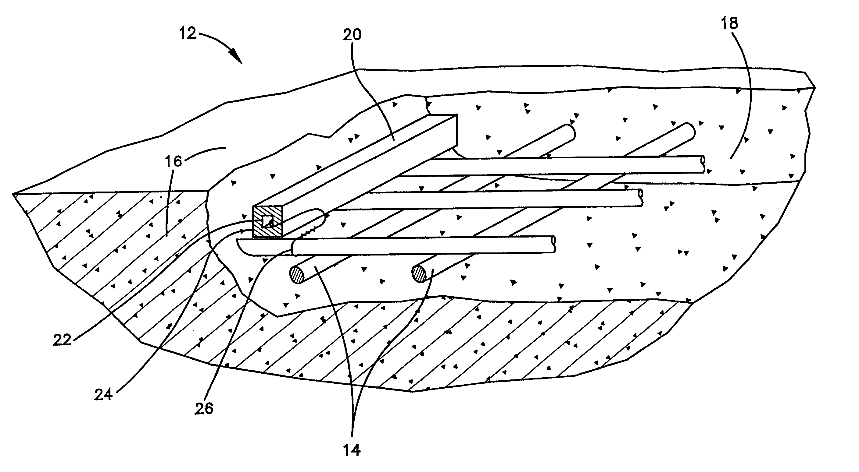
[0065]This Example illustrates the embodiment of FIG. 3. FIG. 3 shows a steel reinforced concrete structure 12, the reinforcement 14 of which is subject to corrosion due to carbonation or ingress of chloride ions from deicing salt or set accelerators. The original concrete 16 of the structure may still be structurally sound, but may be chloride contaminated. A pothole or excavation 18 is representative of damage caused by corrosion of the reinforcement 14, wherein corrosion products have resulted in expansion of the reinforcement 14 and subsequent cracking and delamination of the concrete 16. The concrete 16 is thus in need of patching.

[0066]In the present invention, an assembly 20 is placed in the excavation 18 for the express purpose of preventing corrosion and subsequent delamination of the original concrete 16 outside of the excavation 18. An end of the assembly 20 is shown cut away in cross section to better illustrate the features of the present invention. The assembly 20 cons...


PUM

PropertyMeasurementUnit
concentrationaaaaaaaaaa
diameteraaaaaaaaaa

Abstract

The present invention relates to a method of and an apparatus (20) for cathodic protection of reinforced concrete using discrete anodes (22) in or on the reinforced concrete member (14) to improve performance and service life of the discrete anodes. The discrete anode (22) is embedded in a cementitous grout or mortar (24) to encapsulate the anode (22) and provide contact to complete the cathodic protection circuit. A lithium salt is added to the cementitous grout or mortar (24) in an amount of at least about 0.05 gram per cubic centimeter. The lithium salt functions to enhance the performance of the cathodic protection system (20) by minimizing the deleterious effects of the anode reaction products on the grout or mortar adjacent to the anode and increasing the protective current delivered to the reinforcing steel.

Description

[0001]This application is a continuation-in-part of prior application Ser. No. 09 / 451,173 filed Nov. 30, 1999, now U.S. Pat. No. 6,217,742, which in turn was a continuation-in-part of parent application Ser. No. 09 / 236,731 filed Jan. 25, 1999, now U.S. Pat. No. 6,033,553, Ser. No. 08 / 731,248 filed Oct. 11, 1996 now abandoned and Ser. No. 08 / 839,292 filed Apr. 17, 1997 now U.S. Pat. No. 6,471,851.BACKGROUND OF THE INVENTION[0002]1. Technical Field[0003]This invention relates generally to the field of cathodic protection systems for steel-reinforced concrete structures, and is particularly concerned with the performance of cathodic protection systems utilizing discrete anode elements embedded in cementitous grout or mortar.[0004]2. Description of the Prior Art[0005]The problems associated with corrosion-induced deterioration of reinforced concrete structures are now well understood. Steel reinforcement has generally performed well over the years in concrete structures such as bridges,...

Claims


Application Information

Patent Timeline
Patent Type & Authority Patents(United States)
IPC IPC(8): C23F13/00C23F13/16
CPCC23F13/16C23F2213/22C23F2201/02
Inventor BENNETT, JACK E.
Owner THE EUCLID CHEM CO
Why Eureka
Try Eureka