
Cooling channel formed in a wall

a cooling channel and wall technology, applied in waterborne vessels, climate sustainability, machines/engines, etc., to achieve the effect of optimizing machining operations, improving mechanical strength of walls, and compromising mechanical strength and flow geometry of bottom walls

Inactive Publication Date: 2009-07-23
SN DETUDE & DE CONSTR DE MOTEURS DAVIATION S N E C M A
View PDF1 Cites 4 Cited by
  • Summary
  • Abstract
  • Description
  • Claims
  • Application Information

AI Technical Summary

Benefits of technology

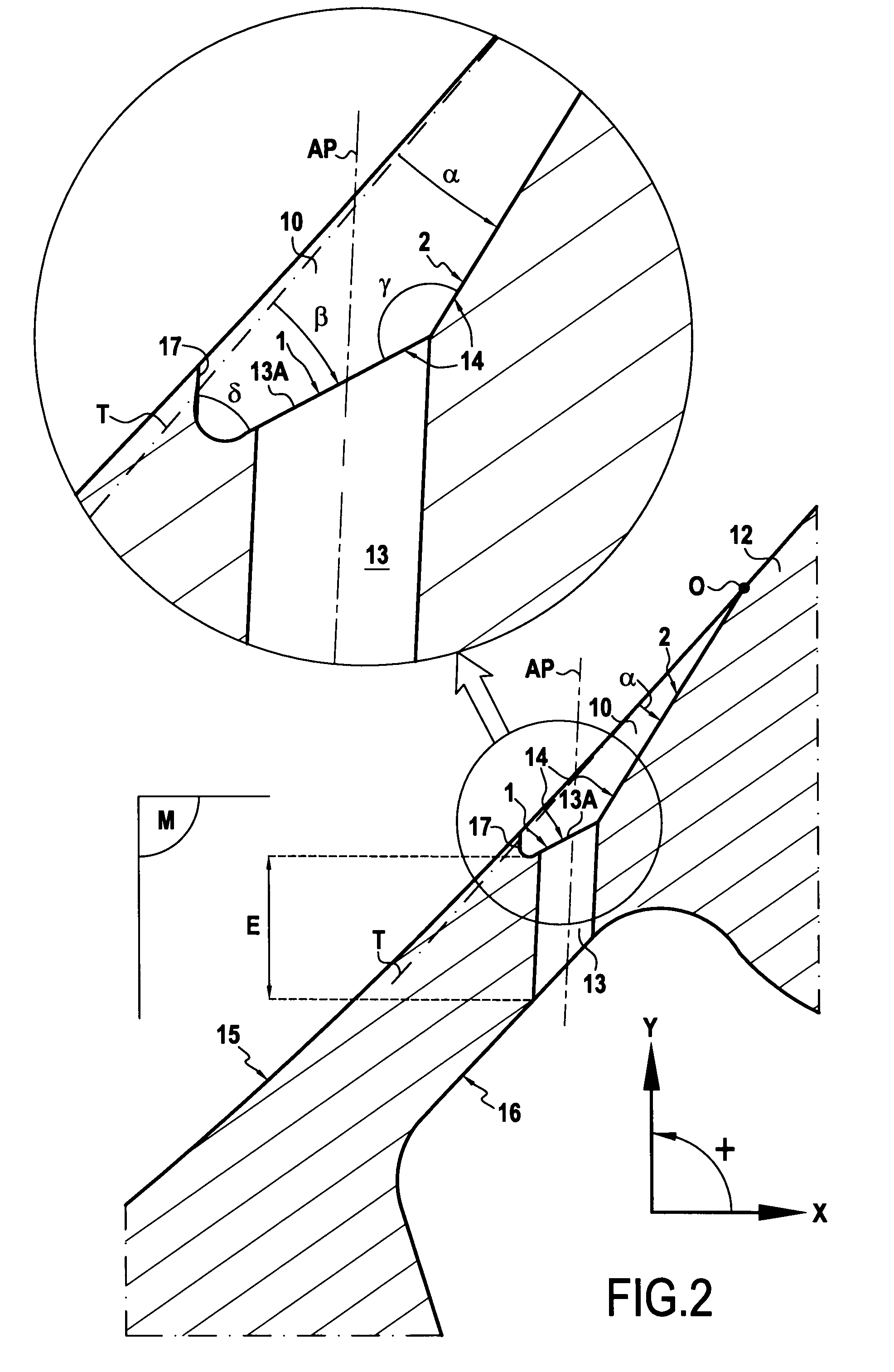
[0009]The wall element of the invention presents the advantage of having a bottom wall of thickness around the hole that is greater than the thickness in known wall elements. Thus, the mechanical strength of said bottom wall against strong and repeated thermal stresses is increased. Furthermore, the overall shape of the diffusion portion conserves good aerodynamic and thermal properties.
[0010]In addition, such a shape for the bottom wall serves to attenuate sharp edges between the bottom wall and the side margin. The first plane portion forms an angle with the side margin that is less acute. Sharp edges are a secondary cause of crack formation and crack starter formation. Attenuating sharp edges therefore improves the mechanical behavior of wall elements.
[0011]The wall element of the invention also presents the advantage of relative decoupling between the shapes of the two plane portions of the bottom wall. As a result, it is easy to adapt the shape of the second plane portion closely to the aerodynamic and thermal constraints set by the designer. Thus, by means of the invention, it is possible to improve the flow of the cooling stream with broader diffusion over the outside surface of the wall. Improved cooling contributes to avoiding excessive thermal stressing of the wall element, and consequently avoids the risk of forming cracks and crack starters. This advantage also improves the mechanical behavior of wall elements compared with prior art wall elements.
[0013]This range of angle values makes it possible firstly to guarantee that the bottom wall is of sufficient thickness, thereby improving the mechanical strength of the wall around said hole, and secondly to guarantee a shape for the bottom wall that enables the fluid to flow in a manner that satisfies requirements for cooling the outside surface of the wall. Thus, by selecting the angle between the second plane portion and the first plane portion to lie in said range of angle values, the compromise between mechanical strength and flow geometry of the bottom wall is improved.
[0014]In an embodiment, the wall element of the invention forms part of the wall of a hollow blade. Under such circumstances, it should be observed that the wall element may belong equally well to a pressure side wall or to a suction side wall, the shape thereof being adapted to both circumstances. This makes it possible to optimize machining operations by using the same tool for making the wall element in the pressure side face and in the suction side face of the blade.

Problems solved by technology

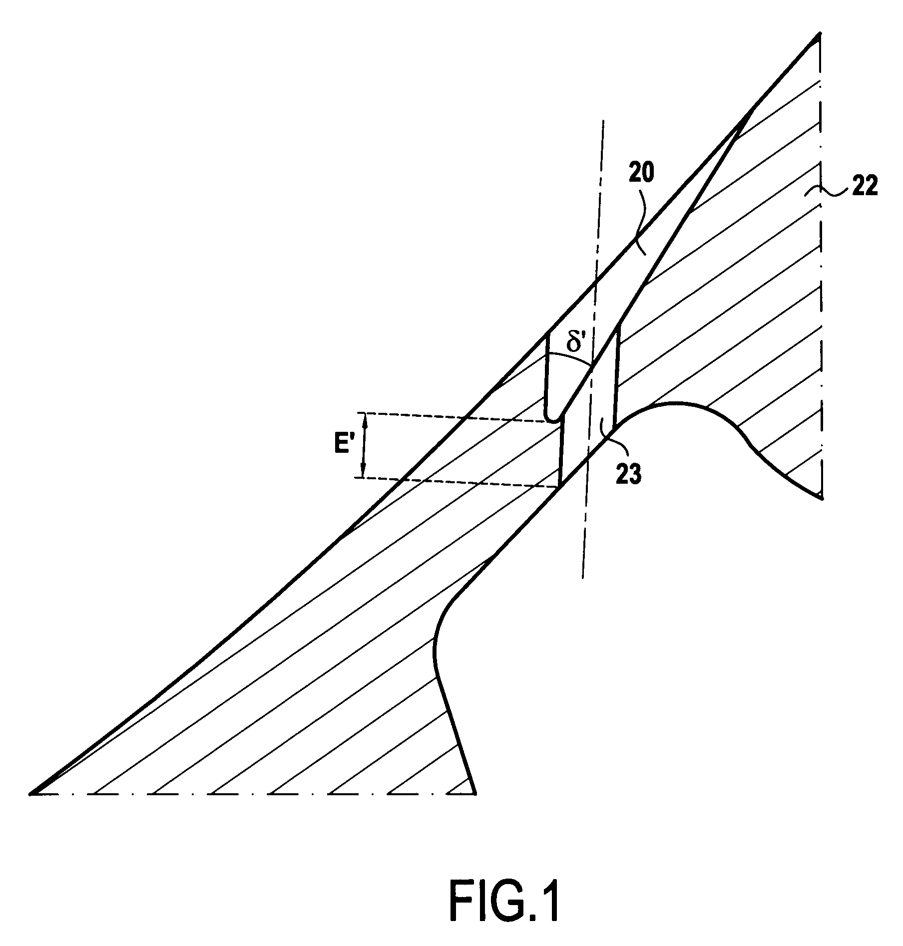
Under strong and repeated thermal stresses, this thinning encourages the local appearance of cracking, and in the long term of cracks that propagate throughout the part.

Method used


Image

  • Cooling channel formed in a wall
  • Cooling channel formed in a wall
  • Cooling channel formed in a wall

Examples


Embodiment Construction

[0027]An embodiment of the wall element is described with reference to FIG. 2. In this example, a wall element 12 having at least one cooling channel formed therein presents an inside surface 16 and an outside surface 15 suitable for being cooled by cool gas flowing in said channel. The channel comprises a hole 13 and a diffusion portion 10. The hole 13 opens out at one end into the inside surface 16, and its other end into the diffusion portion 10, where it forms an orifice 13A. The diffusion portion 10 flares around the orifice 13A and it is defined by a bottom wall 14 and a side margin 17. Said bottom wall 14 presents a first plane portion 1 into which the hole 13 opens out, and a second plane portion 2 situated at the front of the first plane portion 1 in the cool gas flow direction. Said first and second plane portions 1 and 2 are inclined in the thickness of the wall 12. Thus, in the midplane M of the diffusion portion 10 containing the axis AP of the hole, a first angle β mea...


PUM

PropertyMeasurementUnit
angleaaaaaaaaaa
angleaaaaaaaaaa
angleaaaaaaaaaa

Abstract

A wall element having at least one cooling channel formed therein, the wall element presenting an inside surface and an outside surface, the channel comprising a hole and a diffusion portion, the hole opening out at one end in the inside surface, and at the other end in a diffusion portion where it forms an orifice, the diffusion portion flaring around said orifice and being defined by a bottom wall and a side margin. Said bottom wall presents a first plane portion into which the hole opens out, and a second plane portion situated in front of the first plane portion, said first and second plane portions being inclined in the thickness of the wall. The oriented angle of inclination of said first plane portion is less than the positive oriented angle of inclination of said second plane portion.

Description

FIELD OF THE INVENTION[0001]The present invention relates to a wall element, to an electrode for forming said wall element, and to an associated method of fabrication. In particular, the wall may be a wall of a hollow blade of a turbomachine turbine.[0002]More precisely, the present invention relates to a wall element having at least one cooling channel formed therein, said wall element presenting an inside surface and an outside surface suitable for being cooled by cool gas flowing in said channel, the channel comprising a hole and a diffusion portion, the hole opening out at one end into the inside surface, and at its other end, into a diffusion portion by forming an orifice, the diffusion portion flaring around said orifice and being defined by a bottom wall and a side margin.BACKGROUND OF THE INVENTION[0003]Document FR 2 889 089 describes an example of a wall element of the above-specified type forming part of the wall of a hollow blade for an airplane turbojet turbine. FIG. 1 s...

Claims


Application Information

Patent Timeline
Patent Type & Authority Applications(United States)
IPC IPC(8): B64C11/24B21K3/04B23H1/04
CPCB23H1/04B23H9/10Y10T29/49341Y02T50/676F01D5/186Y02T50/60
Inventor BRIERE, ERIC BERNARD DOMINIQUE
Owner SN DETUDE & DE CONSTR DE MOTEURS DAVIATION S N E C M A
Learn More