Flexible seal and molded rigid chamber

a flexible seal and rigid chamber technology, applied in the direction of combustion air/fuel air treatment, machines/engines, transportation and packaging, etc., can solve the problems of excess weight and duct integrity or collapsibility, mold and overmolding does not allow for tight or close part tolerance, and the space between blow-molded and overmold parts is not wide enough to achieve the effect of preventing the movement of the throttle body, reducing noise, and reducing weigh

Inactive Publication Date: 2009-07-23
DENSO INTERNATIONAL AMERICA
View PDF10 Cites 10 Cited by
  • Summary
  • Abstract
  • Description
  • Claims
  • Application Information

AI Technical Summary

Benefits of technology

[0007]An engine air induction system delivers clean air through a throttle body to the engine while providing noise attenuation with minimal power loss by use of an insert molded clean air duct. A dovetail connection exists between an expansion chamber outlet wall and a rubber cuff, which accommodates an inlet portion of a throttle body. The expansion chamber wall may have a dovetail recession while the rubber cuff may have a dovetail projection. Because the rubber cuff is insert molded around the expansion chamber outlet, the interface between the rubber cuff and the expansion chamber, including the dovetail interface, is one of insert molding.
[0008]The dovetail joint between the expansion chamber and cuff prevents separation due to air forces of the air passing through the air induction system en route to the engine. A groove in the cuff, on a side of the cuff opposite of the dovetail projection, receives a protuberance of a throttle body inlet portion. A band clamp fits around the outside diameter of the cuff adjacent and also beside the throttle body inlet protuberance to prevent movement of the throttle body when the clamp is tightened. The cuff may also have a nub or nubs, and / or a ring or rings molded into the inside diameter of the rubber cuff to prevent slippage of the throttle body inlet portion from the rubber cuff.

Problems solved by technology

While such a manufactured product allows for relatively easy attachment to the airbox and throttle body, it also causes concerns related to excess weight and duct integrity or collapsibility.
While such a duct results in a lighter duct, the combination of blow molding and overmolding does not allow for tight or close part tolerances.
This additional length may result in space between the blow-molded and overmolded parts.
Forceful turbulent air entering the induction system may generate an undesirable “whoosh” or “whistle” noise as a result of the forceful air moving through the clean air duct.

Method used


Image

  • Flexible seal and molded rigid chamber
  • Flexible seal and molded rigid chamber
  • Flexible seal and molded rigid chamber

Examples


Embodiment Construction

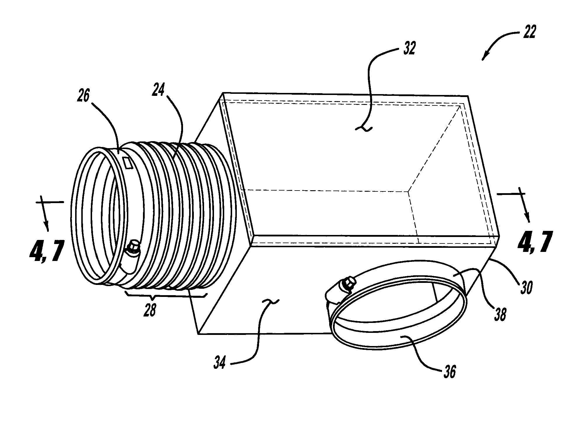
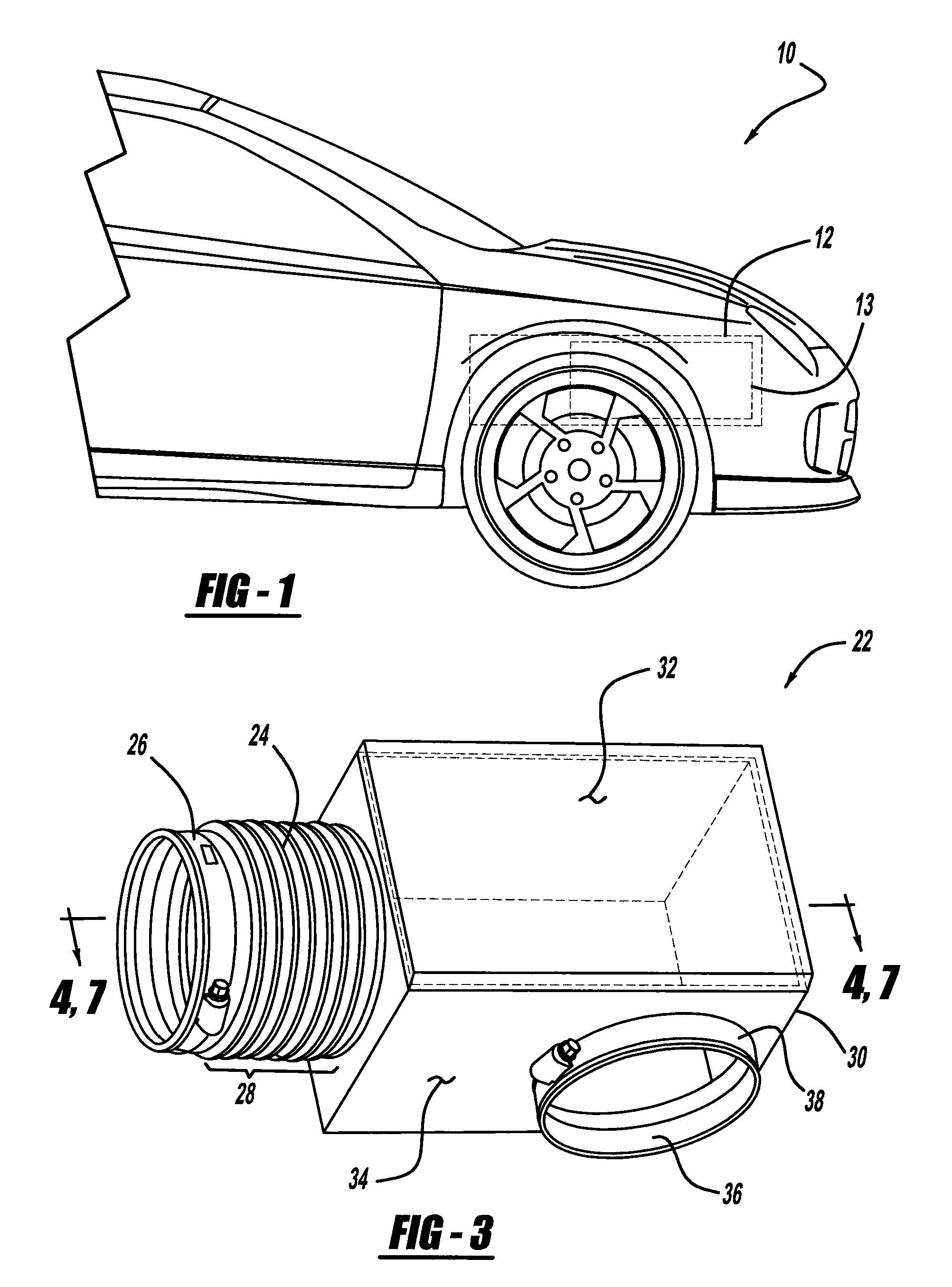
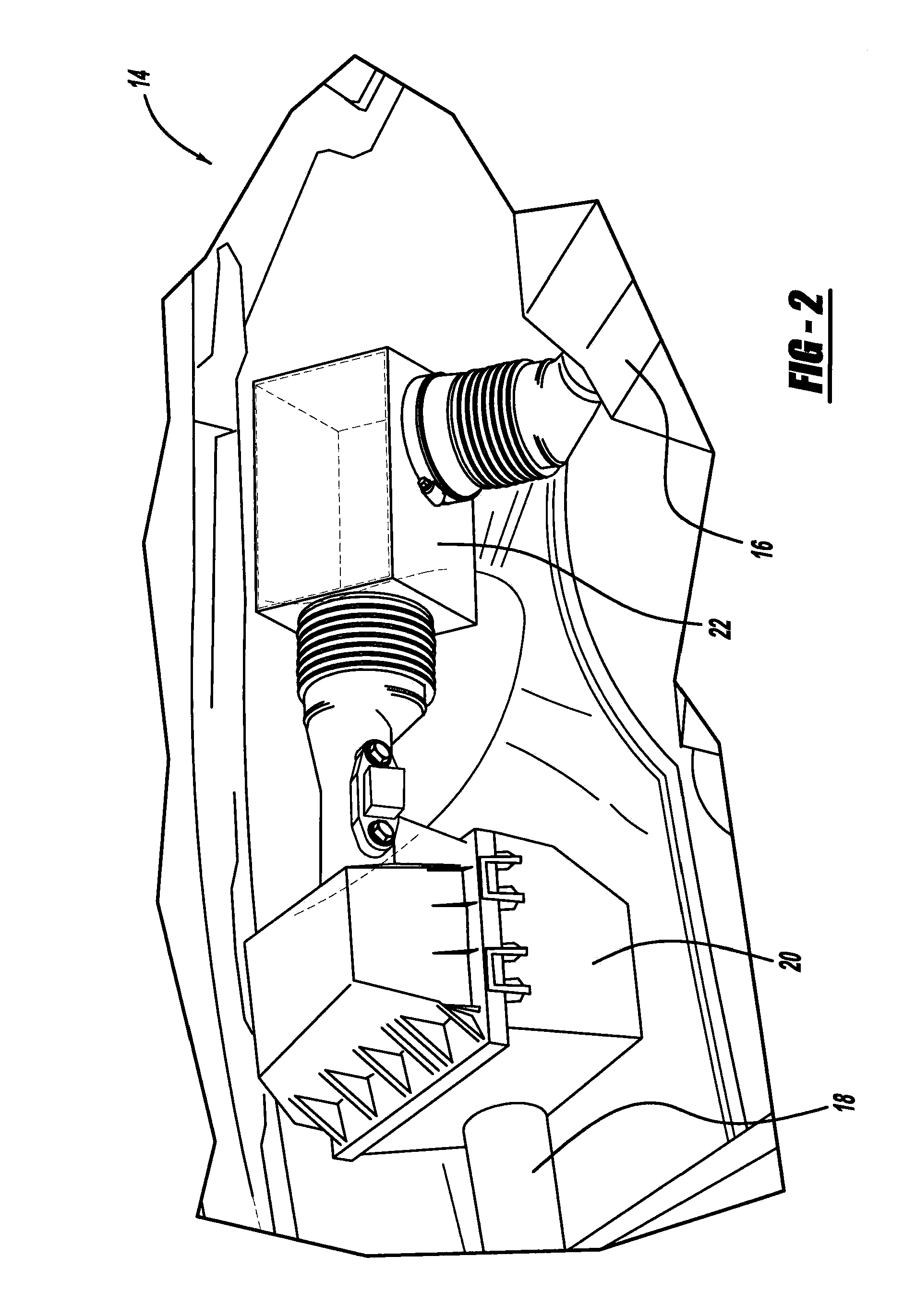
[0020]The following description is merely exemplary in nature and is not intended to limit the present disclosure, application, or uses. With general reference to FIGS. 1-5, the teachings of the present invention will be explained. A typical front end of a representative automotive vehicle 10, includes an underhood compartment 12 for packaging vehicular components. The components of the underhood compartment 12 typically includes a compact array of parts necessary to proper functioning of the vehicle 10, such as an engine 13, an air induction system 14, and more. With reference to FIGS. 1 and 2, the air induction system 14 delivers filtered air to a throttle body 16, which in turn is used in combustion within the vehicle engine 13. The air induction system 14 employs an air duct 18, also known as a fresh, outside or “dirty” air duct, an air intake chamber or airbox assembly 20, and a clean air duct 22. During operation, unfiltered air enters the air induction system 14 through the f...


PUM

PropertyMeasurementUnit
areaaaaaaaaaaa
clamping forceaaaaaaaaaa
weightaaaaaaaaaa

Abstract

A connection between an expansion chamber outlet and a rubber cuff that accommodates an inlet portion of a throttle body exhibits an overmolded, hot plate or spin weld type of connection between an expansion chamber wall outlet portion and the rubber cuff. The rubber cuff may have a bellow in it to absorb shock and force from the throttle body. The rubber cuff may be insert molded around the expansion chamber outlet such that the joined interface between the rubber cuff and the expansion chamber is from the molding. The molded interface prevents separation due to air forces through the chamber and cuff. A cuff recession on a cuff inside diameter receives a protuberance of the throttle body inlet portion. A band clamp fits around the outside diameter of the cuff, adjacent the throttle body inlet protuberance, to prevent movement relative to the throttle body.

Description

CROSS-REFERENCE TO RELATED APPLICATIONS[0001]This application claims priority to, and is a continuation-in-part of, U.S. patent application Ser. No. 11 / 728,633 filed on Mar. 27, 2007. The entire disclosure of application Ser. No. 11 / 728,633 is incorporated herein by reference.FIELD[0002]The present disclosure relates to a vehicle air induction system and more particularly, to an interconnection of an insert-molded expansion chamber and cuff of a clean air duct.BACKGROUND[0003]The statements in this section merely provide background information related to the present disclosure and may not constitute prior art. Air induction systems typically utilize clean air ducts to convey filtered air from an airbox assembly to a throttle body, before delivering the filtered air to a vehicle engine. The clean air duct must be closed to the outside environment to prevent false air from entering the system. False air is any air that enters the system through leaks created within a part or at assemb...

Claims


Application Information

Patent Timeline
Patent Type & Authority Applications(United States)
IPC IPC(8): F16L51/02F16L27/11
CPCB60K13/02F02M35/024F02M35/10137F02M35/1283F02M35/10321F02M35/1034F02M35/1272F02M35/10144
Inventor WILLIAMS, MARK L.
Owner DENSO INTERNATIONAL AMERICA
Why Eureka
Try Eureka