Method for controlling a compression-ignition internal combustion engine and control device for controlling a compression-ignition internal combustion engine

a technology of internal combustion engine and control device, which is applied in the direction of electric control, machines/engines, instruments, etc., can solve the problems of delay or miss in the ignition of fuel, premature ignition, etc., and achieve the effects of reducing fuel consumption, good homogeneous mixture formation, and low combustion temperatur

Inactive Publication Date: 2009-07-23
ROBERT BOSCH GMBH
View PDF1 Cites 17 Cited by
  • Summary
  • Abstract
  • Description
  • Claims
  • Application Information

AI Technical Summary

Benefits of technology

[0024]In a preferred specific embodiment, the compression-ignition internal combustion engine is an Otto engine. The compression-ignition internal combustion engine implemented as an Otto engine is distinguished in relation to typical external ignition methods by a reduced fuel consumption, in particular within the partial-load range. In addition, the Otto engine allows very good homogeneous mixture formation, a plurality of exothermic centers in the combustion chamber, and a low combustion temperature with a CAI method. This results in a very uniform and rapidly occurring combustion having a reduced pollutant emission, in particular in comparison to the laminar operation, which also saves fuel. A comparatively costly exhaust post-treatment system (e.g., in regard to nitrogen oxides) may thus be dispensed with.

Problems solved by technology

For example, an excessively late ignition of the fuel in the first cycle may trigger a premature ignition during the second cycle.
A premature ignition during the first cycle correspondingly frequently causes a delay or a miss in the ignition of the fuel during the second cycle.

Method used


Image

  • Method for controlling a compression-ignition internal combustion engine and control device for controlling a compression-ignition internal combustion engine
  • Method for controlling a compression-ignition internal combustion engine and control device for controlling a compression-ignition internal combustion engine
  • Method for controlling a compression-ignition internal combustion engine and control device for controlling a compression-ignition internal combustion engine

Examples


first embodiment

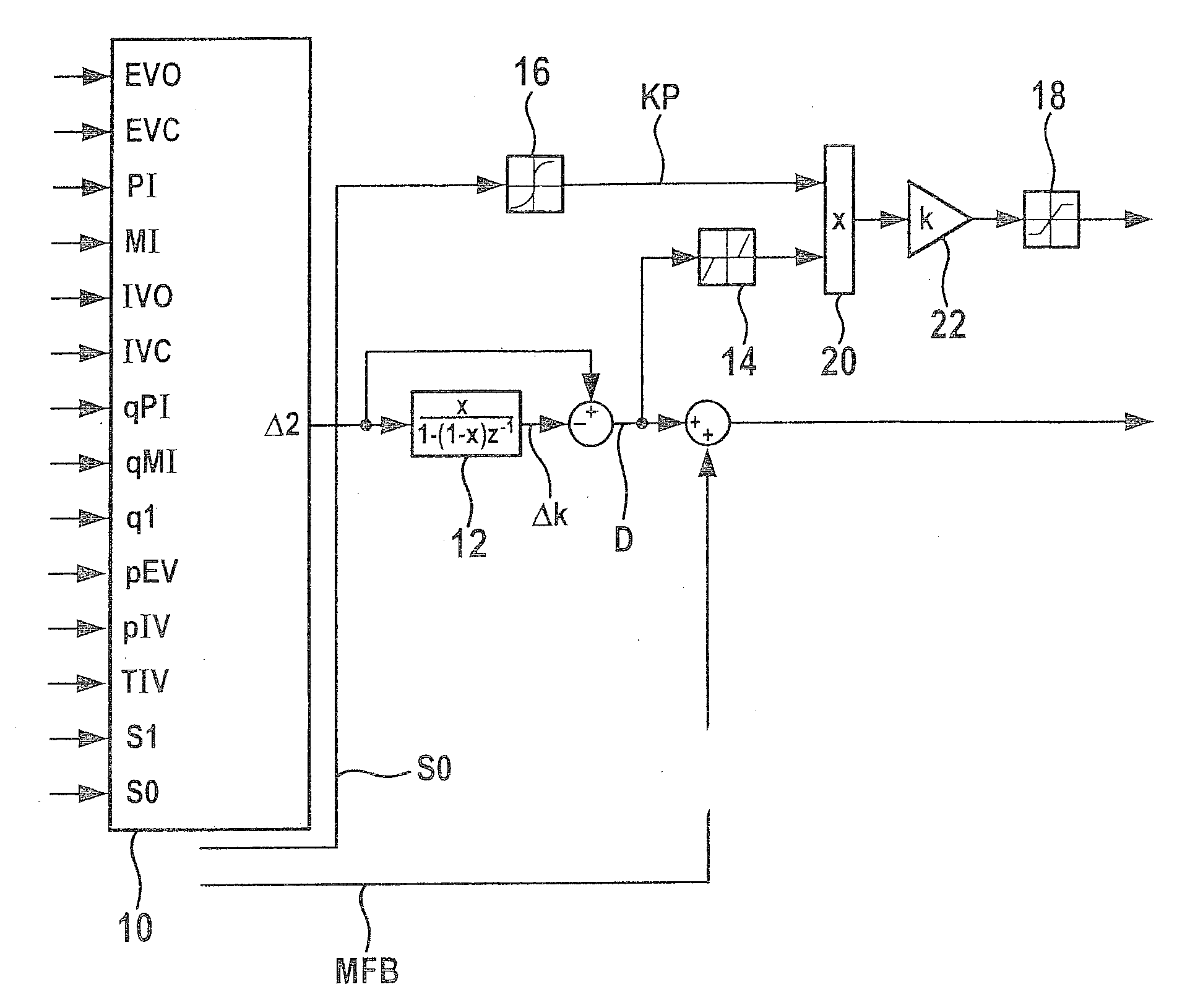
[0029]FIG. 1 shows a block diagram illustrating the method for controlling a compression-ignition internal combustion engine. The method is shown after at least one first cycle has occurred. The fuel ignition of the first cycle has already occurred before the beginning of the method.

[0030]In a first step of the method shown in FIG. 1, a setpoint combustion point S0 is provided to a computer unit 10. Setpoint combustion point S0 may be provided during travel while taking a current load and / or a current speed of the associated vehicle into consideration. Setpoint combustion point S0 is, for example, a setpoint ignition point in time, a setpoint feature during a combustion phase, a setpoint temperature feature during the combustion phase, and / or a setpoint 50% mass conversion point, such as a setpoint MFB50. The setpoint combustion point may be specified as a crankshaft angle.

[0031]An actual combustion point Si of the first cycle, ascertained using a sensor (not shown), is also provide...

second embodiment

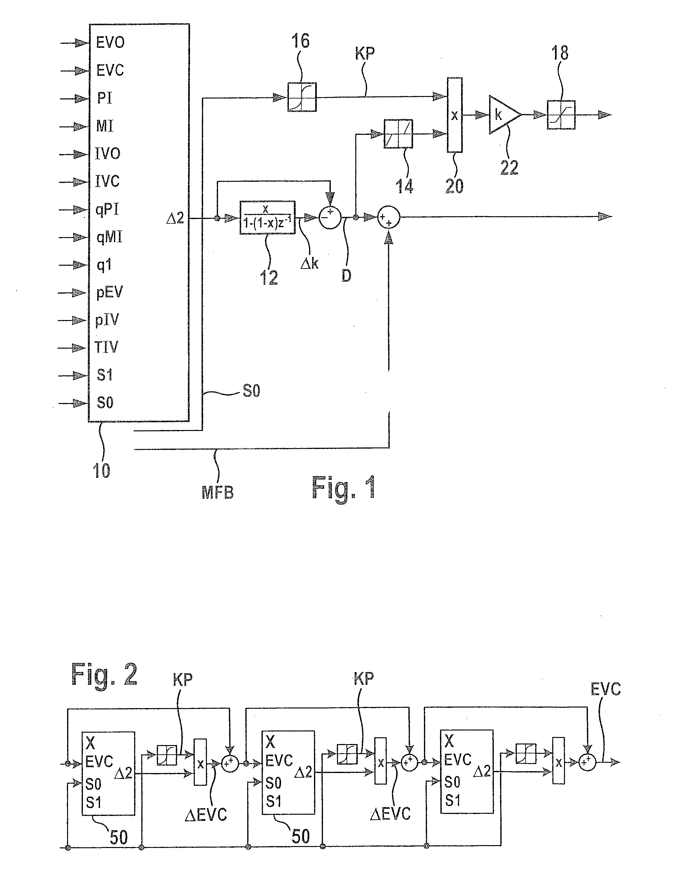
[0047]FIG. 2 shows a block diagram illustrating the method for controlling a compression-ignition internal combustion engine.

[0048]The second embodiment relates to a cascading method for a data-driven model. The model preferably includes kernel-based, statistical learning methods (Gaussian processes or support vector machines) and / or neural networks. In the cascading method, an update of probable deviation Δ2 and the calculation of correction ΔEVC for the exhaust valve closing time are executed multiple times one after another, particular calculated correction ΔEVC for the exhaust valve closing time being taken into consideration to update probable deviation Δ2. For the sake of better clarity, the subtraction of the low-pass filtered probable deviation and the dead center element described above are not shown.

[0049]In a first step of the method, a data model 50, whose function is described in greater detail below, is provided. Data model 50 is stored, for example, on a computer unit...

third embodiment

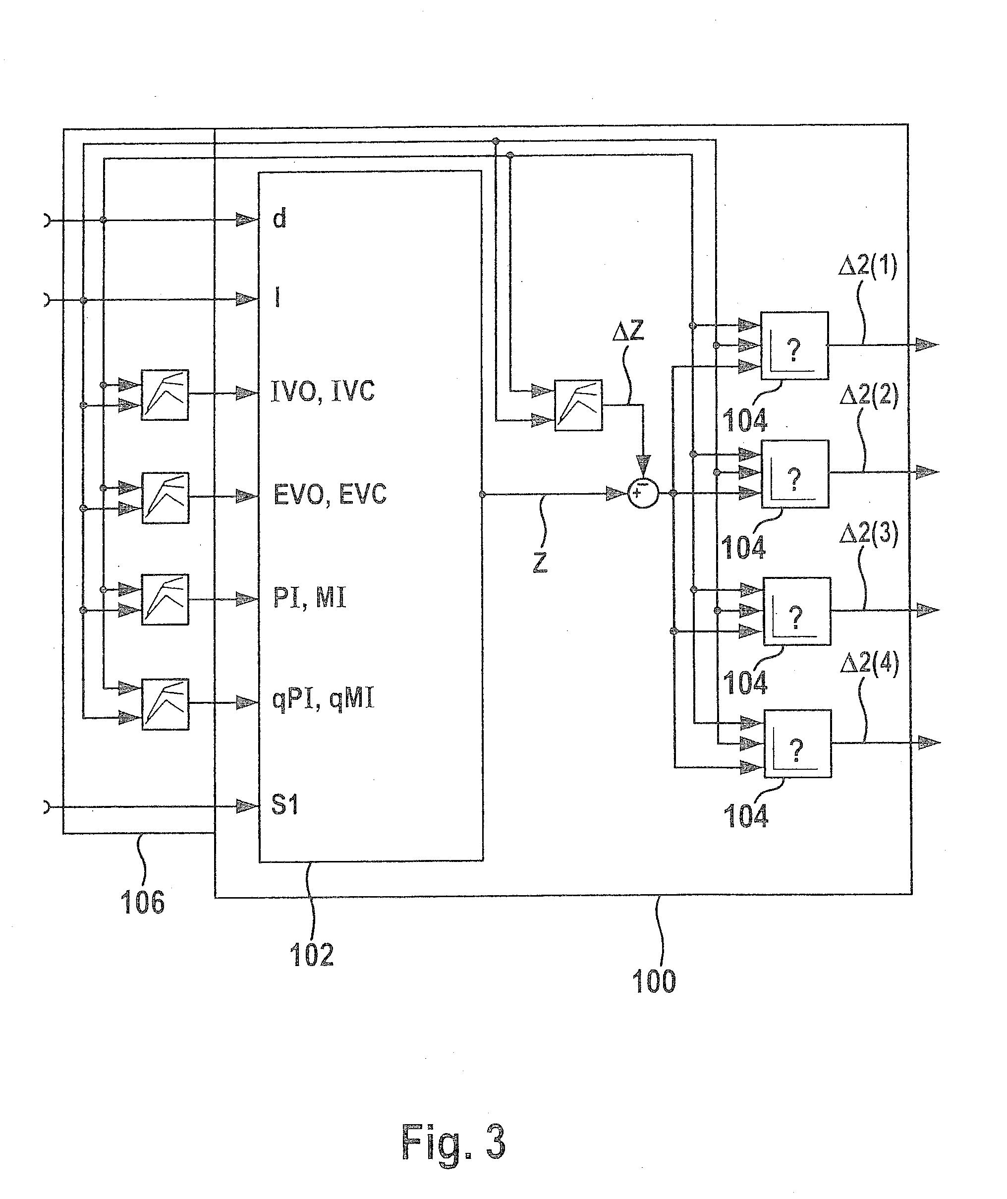
[0056]FIG. 3 shows a block diagram illustrating the method for controlling a compression-ignition internal combustion engine.

[0057]Calculation model 100 explained on the basis of FIG. 3 includes a basic calculation model 102 for calculating a cylinder-independent state variable and multiple cylinder models 104, each for a cylinder of an associated internal combustion engine (not shown). Four cylinder models 104 for a compression-ignition internal combustion engine having four cylinders are shown as an example.

[0058]Calculation model 100 additionally also includes a unit for determining control parameter 106 as a function of the operating point. The unit for determining control parameter 106 as a function of the operating point is designed to ascertain a rotational speed d and a load l during travel of the associated vehicle. As an alternative thereto, rotational speed d and load l may also be output from a central vehicle control system via a vehicle bus to the unit for determining ...


PUM


Abstract

A method for controlling a compression-ignition internal combustion engine includes the following steps: predefining a setpoint combustion point for the compression-ignition internal combustion engine, predefining a calculation model for calculating a probable deviation of a future cycle of the internal combustion engine from the predefined setpoint combustion point while taking an ascertained actual combustion point of a completed cycle of the internal combustion engine into consideration, predefining a mean deviation for the internal combustion engine, operating the internal combustion engine for a first cycle and ascertaining an actual combustion point of the first cycle, calculating a probable deviation of a second cycle, which occurs after the first cycle, of the internal combustion engine from the predefined setpoint combustion point, comparing the calculated probable deviation of the second cycle to the predefined mean deviation, and ascertaining at least one operating variable for operating the internal combustion engine at least during the second cycle as a function of the comparison. In addition, a control device for controlling a compression-ignition internal combustion engine is described.

Description

FIELD OF INVENTION [0001]The present invention relates to a method for controlling a compression-ignition internal combustion engine. Furthermore, the present invention relates to a corresponding control device for controlling a compression-ignition internal combustion engine.BACKGROUND INFORMATION [0002]In an Otto-engine combustion method, which is frequently referred to in the literature as a gasoline HCCI method (homogeneous charge compression ignition) or as a CAI method (controlled auto ignition), a fuel injected into an internal combustion engine is combusted without external ignition. The fuel is instead automatically ignited by mixture of the injected fuel with a hot exhaust gas and subsequent compression of the fuel-gas mixture.[0003]CAI engines are typically equipped with a variable valve drive and a gasoline direct injection. One differentiates between a fully-variable valve drive, implemented by an electrohydraulic valve controller, for example, and a partially-variable ...

Claims


Application Information

Patent Timeline
Patent Type & Authority Applications(United States)
IPC IPC(8): F02D41/00
CPCF02D35/02F02D35/023F02D2041/1433F02D2041/001F02D2041/1432F02D35/028F02D35/021F02D35/025F02D2041/1412
Inventor LOEFFLER, AXELFISCHER, WOLFGANGKARRELMEYER, ROLANDGRAF, GERALD
Owner ROBERT BOSCH GMBH
Why Eureka
Try Eureka