Method of and apparatus for testing wooden poles

a technology for wooden poles and testing methods, applied in the direction of weighing apparatus, analysing solids using ultrasonic/ultrasonic/infrasonic waves, and processing detected response signals, etc., can solve the problems of pole replacement, increased cost and possible delay, and reducing the safe working life of the pol

Inactive Publication Date: 2009-07-30
CPI QUETRA
View PDF9 Cites 30 Cited by
  • Summary
  • Abstract
  • Description
  • Claims
  • Application Information

AI Technical Summary

Benefits of technology

[0021]This technique is also aided by the high impedance mismatch between the wood and air, between wood and the ground, in the case of a pole having an end buried in the ground, and by the aspect ratio of the poles (for utility poles the typical ratio of length to diameter is about 30:1). Typically these lead to relatively large Q values for good quality poles (e.g. 30), thereby enabling the detection of pole decay when the ideal conditions for the excitement of transverse waves, and the establishment of transverse mode standing waves, deteriorate. (Q is the quality factor, conventionally defined asQ=f0Δf,where f0 is the resonant frequency and Δf is the bandwidth at −3 dB from the peak.)
[0022]The technique is especially effective below ground, effectively measuring the increased loss of energy from (a) a decay pocket leaking energy into the ground due to the reduced acoustic impedance mismatch between the pole and the ground (if the impedances of the decayed wood and the ground were the same, all the sound would escape and there would be no resonance) and / or (b) the soft spongy nature of the decayed wood increasing inherent acoustic absorption.
[0026]The apparatus may incorporate a Global Positioning System (GPS) receiver to enable the time and position of the tests to be accurately recorded. In the case of utility poles, since they are rarely closer together than the 1 metre resolution typically achievable, this will eliminate the need to identify the pole number.

Problems solved by technology

In some conditions, and / or where treatment of the timber has been insufficient after cutting, rot can occur, substantially reducing the safe working life of the pole.
If the pole is deemed unsafe for ladder access, the work may need to be carried out from an access hoist, which involves extra cost and possible delay, but it may become necessary for the pole to be replaced, which is even more costly.
Furthermore, the high-energy pulses required, typically delivered manually, to generate sufficient acoustic power cause local damage to the structure.
In some instances, the results obtained were no more accurate than could be obtained by a trained person listening to the sound.
A major disadvantage of this technique is that it necessitates the cutting of slots into the pole, something that utilities operators would consider highly undesirable, since it would tend to weaken the pole and to provide a possible future route into the interior of the pole of damaging moisture and attacking organisms.

Method used


Image

  • Method of and apparatus for testing wooden poles
  • Method of and apparatus for testing wooden poles
  • Method of and apparatus for testing wooden poles

Examples


Embodiment Construction

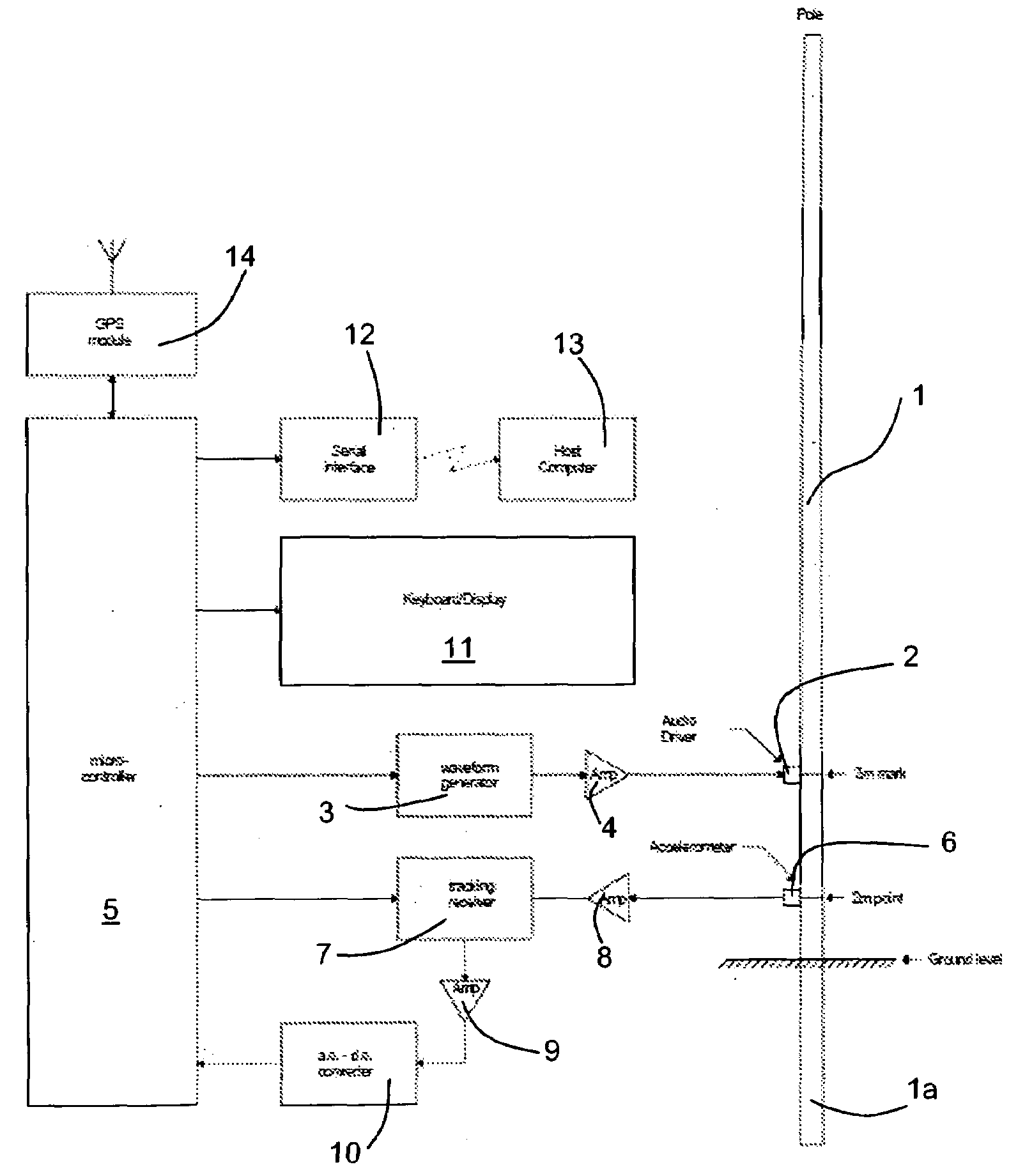
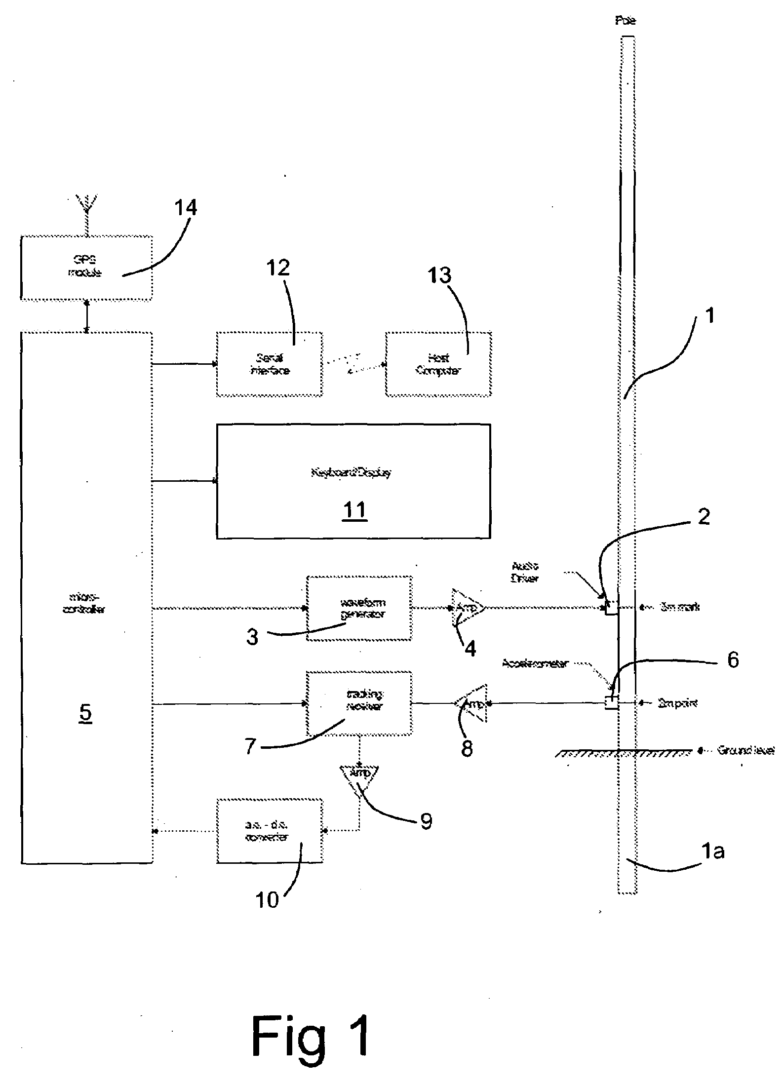
[0038]Referring first to FIG. 1, a utility pole 1 has one end thereof 1a buried in the ground. If decay occurs in the buried end 1a, the pole may become inadequately supported and could fail when abnormally loaded, for example by a maintenance engineer climbing a ladder placed against it. The test apparatus consists of a transmit transducer 2 in the form of a magnetostrictive actuator which is temporarily clamped against the surface of the pole, for example at the 3 metre mark relative to the lowermost end, by means of a removable strap, for example. The driving signal for the transducer 2 is supplied by a waveform generator 3 by way of an amplifier 4. The waveform generator is controlled by a microcontroller 5.

[0039]A receive transducer 6, for example an accelerometer, is similarly temporarily clamped to the external surface of the pole 1 at a distance from the transmit transducer 2. For example, it can be mounted at the 2 metre position from the end of the pole. The output from th...


PUM

PropertyMeasurementUnit
frequencyaaaaaaaaaa
frequenciesaaaaaaaaaa
lengthaaaaaaaaaa

Abstract

A method of testing an elongate wooden element comprises injecting an input acoustic signal into the element, detecting a return acoustic signal at a surface of the element, and determining a spectral profile for the return signal. In at least a predetermined range in the spectral profile, each resonance peak is detected whose amplitude exceeds a first predetermined value, and from the resonance peaks so detected the number of higher peaks is determined whose amplitude exceeds 3 dB. For each of said higher peaks a quality factor Q is calculated, a mean quality value Qm is determined, and Qm is then compared with a predetermined value to provide an indication of the presence or absence of external decay of the element. A ratio R of the number of higher peaks to the number of resonance peaks detected, and the statistical spread S of the average Q for the spectral profile, are calculated and compared with a predetermined boundary function Fn(R,S) to determine acceptability or unacceptability of the pole.

Description

FIELD OF THE INVENTION[0001]This invention relates to a method of and an apparatus for testing wooden poles and other wooden structural elements, for example to detect degradation due to rot.BACKGROUND TO THE INVENTION[0002]While the invention relates to the testing of wooden structural elements in general, one common example of a structural element that needs monitoring is the utility pole. Utility poles are typically a length of the trunk of a pine tree. After cutting, the poles are seasoned for sufficient time to dry and stabilise the timber, and are then treated with preservative chemicals. The poles are intended to have a pre-determined length buried in the ground, to provide sufficient structural stability. In some conditions, such poles can remain serviceable for many years—some have remained sound for several decades.[0003]In some conditions, and / or where treatment of the timber has been insufficient after cutting, rot can occur, substantially reducing the safe working life ...

Claims


Application Information

Patent Timeline
Patent Type & Authority Applications(United States)
IPC IPC(8): G01N29/44
CPCG01N29/11G01N29/2412G01N29/4427G01N29/46G01N2291/102G01N2291/02466G01N2291/0421G01N2291/0422G01N2291/048G01N33/46G01B17/00G01N29/12
Inventor GREENOUGH, RODNEY DAVIDMORAN, JOHN ANTHONY
Owner CPI QUETRA
Why Eureka
Try Eureka