Process for the heat treatment of steel products

Active Publication Date: 2009-07-30
MESSER IND USA INC
View PDF2 Cites 12 Cited by
  • Summary
  • Abstract
  • Description
  • Claims
  • Application Information

AI Technical Summary

Benefits of technology

[0006]Therefore, it is an object of the present invention to develop a process for the he

Problems solved by technology

In particular in the convection zone, the degree of oxidation is difficult to control, since the temperature profile in this zone is dependent, inter alia, on the length of the convec

Method used


Image

  • Process for the heat treatment of steel products
  • Process for the heat treatment of steel products
  • Process for the heat treatment of steel products

Examples


Example

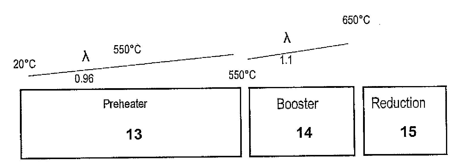
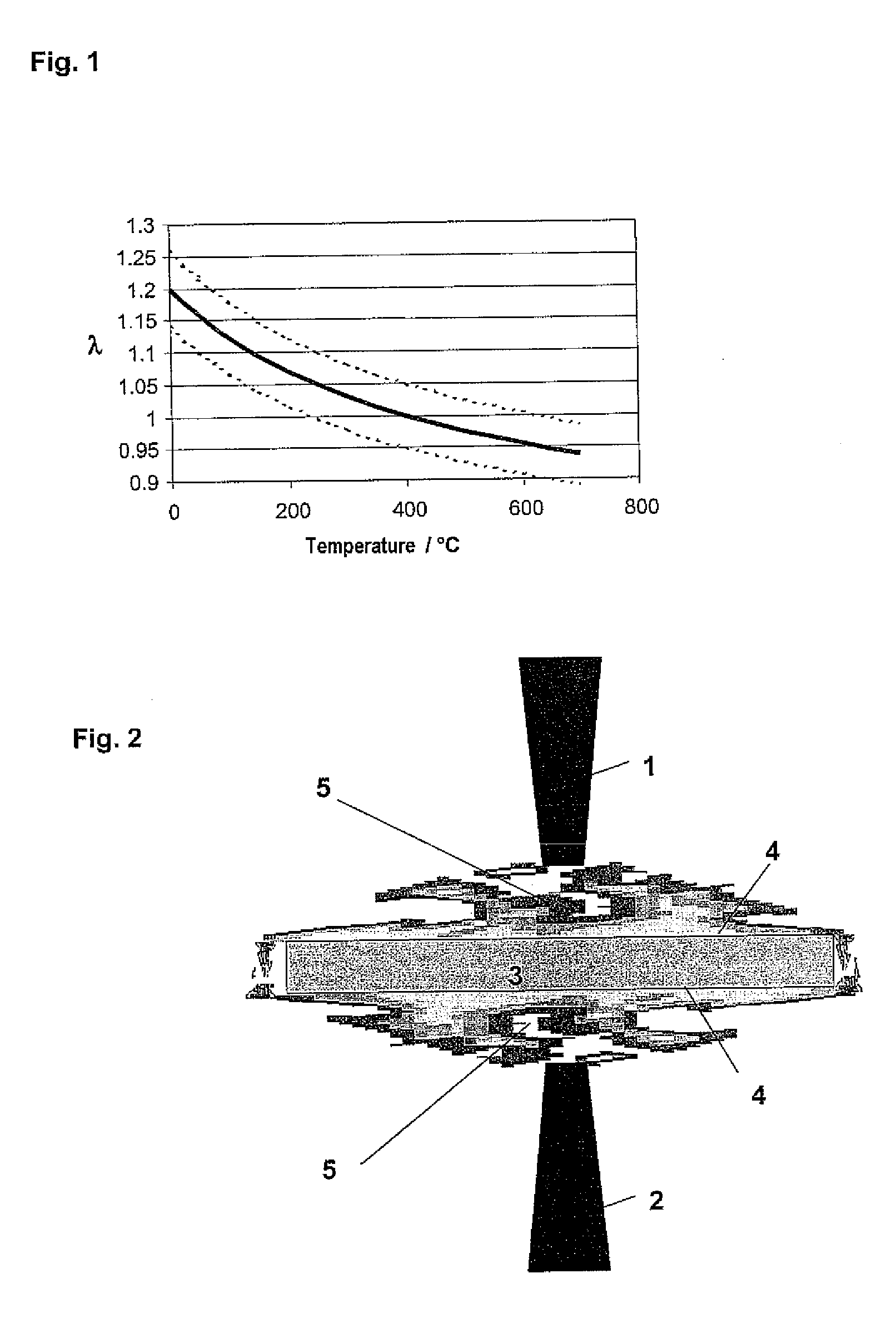
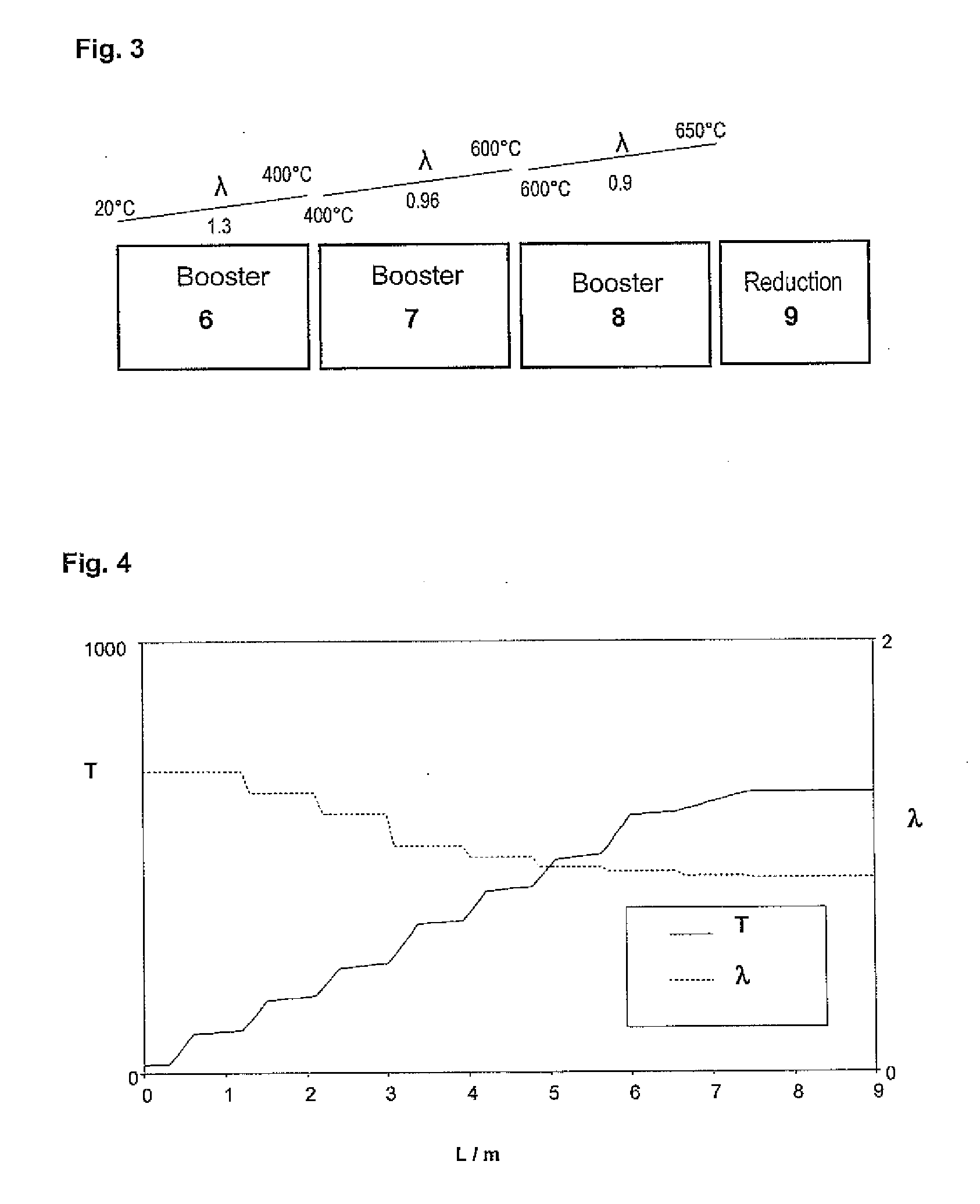
[0038]FIG. 2 shows two booster burners 1, 2 which are used in accordance with the invention to heat a steel strip 3 from a starting temperature to a target temperature. The strip 3 is conveyed through a continuous furnace (not shown) in a direction perpendicular to the plane of the drawing. The burners 1, 2 are arranged perpendicular to the conveying direction and perpendicular to the strip surface 4. The flames 5 generated by the booster burners 1, 2 enclose the entire cross section of the steel strip 3. Within the flames 5, the stoichiometry is set in a defined way as a function of the starting temperature and the target temperature. The enclosing flames 5 according to the invention ensure a uniform, defined heating and treatment of the steel strip 3.

[0039]The process according to the invention is preferably used to clean and / or heat steel products in strip form in continuous furnaces. The invention offers particular advantages for the heating or pretreatment of steel products pri...


PUM

PropertyMeasurementUnit
Temperatureaaaaaaaaaa

Abstract

The invention provides a process for the heat treatment of steel products, in particular of steel strips or sheets, in which the product is brought from a starting temperature to a target temperature in a booster zone having at least one burner; the burner is operated with a fuel, in particular a fuel gas, and an oxygen-containing gas which contains more than 21% oxygen; and the product is brought into direct contact with the flame generated by the burner, the air ratio λ within the flame being set as a function of the starting temperature and/or the target temperature.

Description

[0001]The invention relates to a process for the heat treatment of steel products, in particular of steel strips or sheets.[0002]To produce coated (e.g. hot-dip galvanized) steel strips, the strips to be coated are first of all cleaned, are heated in a continuous furnace and are then annealed in a reducing atmosphere to produce the desired materials properties. This is followed by the actual coating operation in a suitable melt bath or using an appropriate process.[0003]During the heating phase in the continuous furnace, the steel is to be heated under defined conditions in order to allow better setting of the required properties in the subsequent process steps. Depending on the type of steel used, it may be expedient for the oxidation to be minimized or to deliberately effect a certain degree of oxidation.[0004]Hitherto, the heating of the steel strips has been carried out in continuous furnaces in which the steel strips pass through a convection zone and a heat-up zone. In the hea...

Claims


Application Information

Patent Timeline
IPC IPC(8): C21D8/02F26B25/00
CPCC21D1/52C21D9/46C21D9/561F27D99/0033C21D11/00F27D19/00C21D9/63C21D9/56F27B9/12F27B9/36F27D2019/0043C21D9/00
Inventor EICHELKRAUTH, HERBERTHEILER, HANS-JOACHIMHOGNER, WERNERJINDRA, FREDRAINHARD, PAULRITZEN, OLA
Owner MESSER IND USA INC
Why Eureka
Try Eureka