Light emitting diode with higher illumination efficiency

a technology of light-emitting diodes and illumination efficiency, which is applied in the direction of basic electric elements, electrical apparatus, and semiconductor devices, etc., can solve the problems of difficult to differentiate high-brightness, affecting individual working efficiency or vision, and affecting people's physical and mental health, so as to achieve higher light-emitting efficiency, increase light-emitting efficiency, and improve light-emitting efficiency

Active Publication Date: 2009-07-30
EPISTAR CORP
View PDF1 Cites 11 Cited by
  • Summary
  • Abstract
  • Description
  • Claims
  • Application Information

AI Technical Summary

Benefits of technology

[0007]Therefore it is a primary object of the present invention to provide a light emitting diode with higher light emitting efficiency that includes an optical layer such as a light-guiding layer, a light reflective layer or an energy-conversion layer arranged on bottom of the LED chip for increasing light emitting efficiency.
[0008]It is another object of the present invention to provide a light emitting diode with higher light emitting efficiency that includes a rough layer disposed between LED chip and the optical layer so as to increase surface area of the LED chip. Thus light emitted from the LED chip enters the optical layer more easily and the light emitting efficiency of the LED is improved.
[0009]In order to achieve above objects, the present invention provides a light emitting diode that increases illumination efficiency of light source. The LED consists of a LED chip and an optical layer arranged bottom of the LED chip. The optical layer can be a light-guiding layer, a light reflective layer or an energy-conversion layer that increases illumination efficiency of the LED. Moreover, a rough layer is disposed between the LED chip and the optical layer to increase surface area of the LED chip. Thus light from the LED chip enters the optical layer more easily and illumination efficiency of the LED is further improved.

Problems solved by technology

It's difficult to differentiate the high brightness LED and the general LED correctly.
Without sufficient light or brightness, individual's working efficiency or vision may be affected.
This also has negative effects on people's physical and mental health.

Method used


Image

  • Light emitting diode with higher illumination efficiency
  • Light emitting diode with higher illumination efficiency
  • Light emitting diode with higher illumination efficiency

Examples


Embodiment Construction

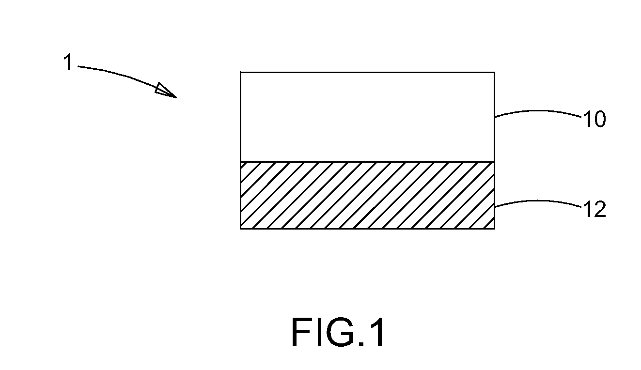
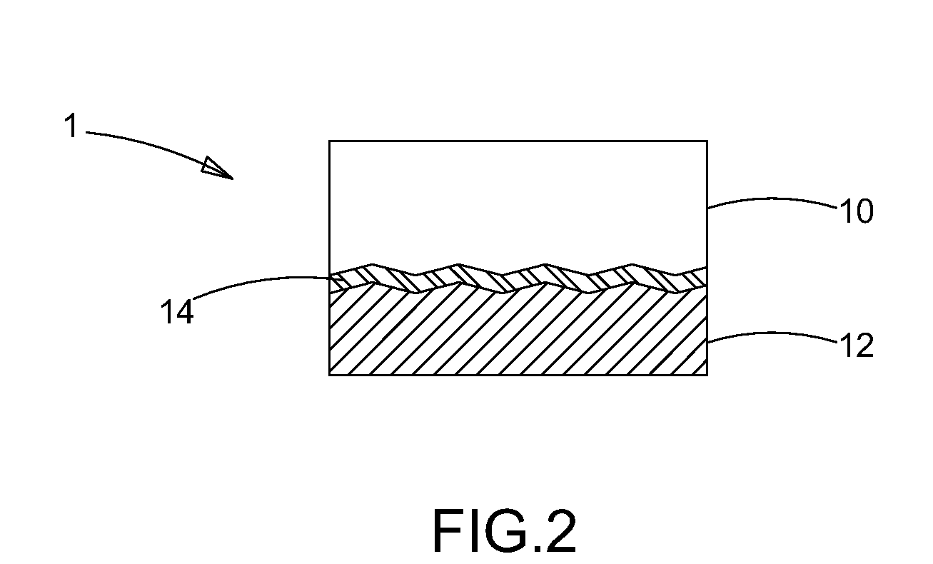
[0026]Refer to FIG. 1, a light emitting diode 1 with higher illumination efficiency is composed of a light emitting diode (LED) chip 10 and an optical layer 12 that is disposed on the bottom of the LED chip 10. The optical layer 12 can be a light-guiding layer, a light reflective layer or an energy-conversion layer and the minimum thickness thereof is 5 um. Refer to FIG. 2, another embodiment is revealed. The LED 1 of this embodiment further includes a rough layer 14 that is arranged between the LED chip 10 and the optical layer 12. The surface roughness of the rough layer 14 ranges from 0.5 nm to 150 nm so as to effectively increase surface area of the LED 1, improve heat dissipation effect and reduce reflection of the light from the LED chip 10. Moreover, the light from the LED chip 10 gets more easily to enter the optical layer 12 so that the light emitting efficiency is improved.

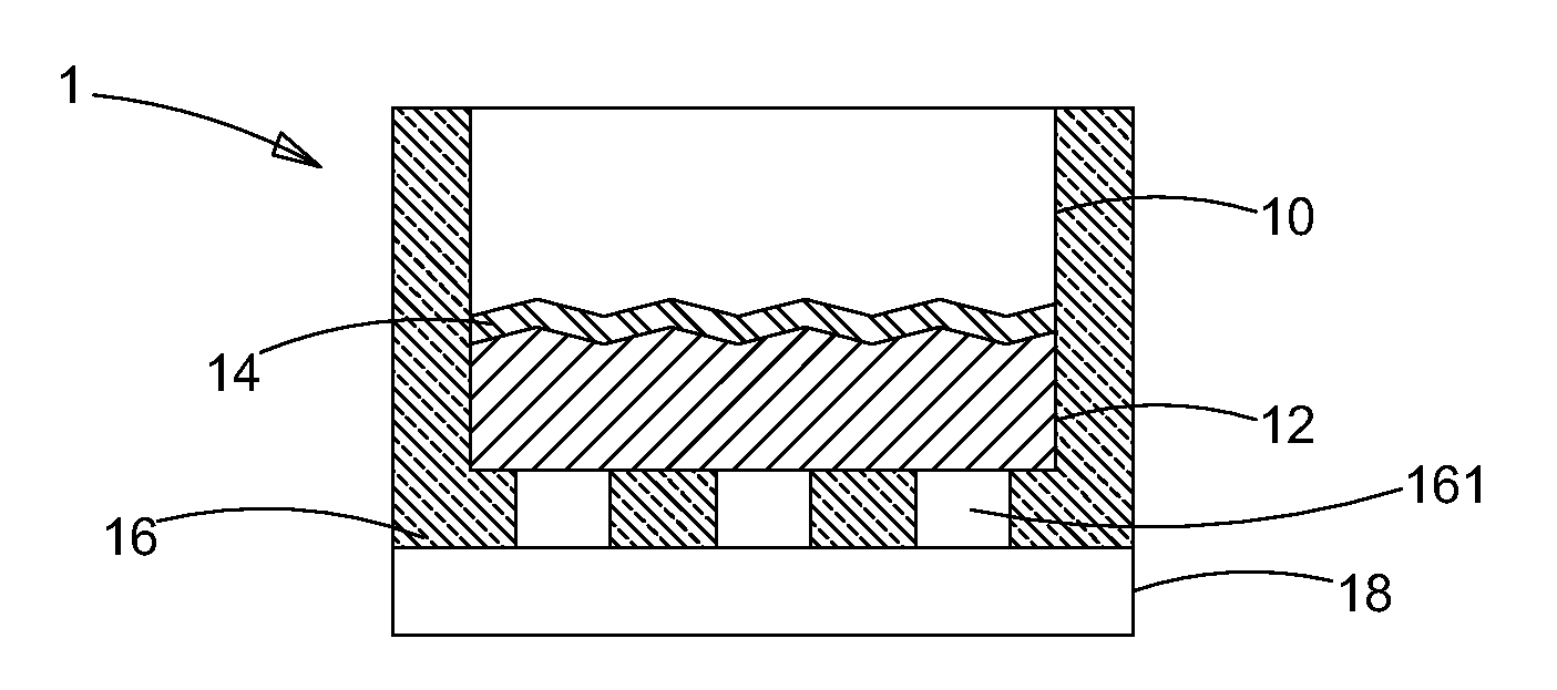
[0027]Refer to FIG. 3A&FIG. 3B, a further embodiment is disclosed. A LED 1 that increases illuminatio...


PUM


Abstract

A light emitting diode (LED) with higher illumination efficiency is revealed. The LED includes a LED chip and an optical layer arranged on the bottom of the LED chip. The optical layer is a light-guiding layer, a light reflective layer or an energy-conversion layer that increases light emitting efficiency of the LED. Furthermore, a rough layer is disposed between the LED chip and the optical layer so as to increase surface area of the LED chip. Thus light emitted from the LED chip enters the optical layer more easily and the illumination efficiency of the LED is increased.

Description

BACKGROUND OF THE INVENTION[0001]The present invention relates to a light emitting diode, especially to a light emitting diode that increases illumination efficiency of light source.[0002]Light emitting diode (LED) is a fine solid-state light source made of semiconductor material. The light source includes two electrodes. After being applied with voltage (minimum current), the electron-hole recombination process produces some photons due to energy gap of electrons and electron-holes when electrons cross the junction from the n- to the p-type material. The LED is different from a general light bulb and it features on low power consumption, with long lifetime, low driving voltage, and fast reaction. Moreover, the LED has compact volume, and good shock resistance so that it's suitable for mass production in the form of mini or array-type elements. It has been applied to electrical appliances, computers and communication products and has become one of the essentials in our daily lives.[...

Claims


Application Information

Patent Timeline
Patent Type & Authority Applications(United States)
IPC IPC(8): H01L33/00H01L33/22H01L33/44H01L33/50H01L33/60
CPCH01L33/22H01L33/60H01L33/508H01L33/44H01L2224/32257H01L2224/32245H01L2224/48247H01L2224/48257H01L2224/73265H01L2224/45139H01L2924/00014H01L2924/00011H01L2924/00H01L2224/45015H01L2924/207H01L2924/01049
Inventor PAN, SHYI-MINGCHENG, WEI-KANGHUANG, KUO-CHIN
Owner EPISTAR CORP
Why Eureka
Try Eureka