Light diffuser plate, surface light source, and liquid crystal display
a technology of light diffuser plate and surface light source, which is applied in the direction of lighting device details, lighting and heating apparatus, instruments, etc., can solve the problem of yellowish color tone of conventional light diffuser plate, and achieve the effect of reducing cost, high quality, and sufficient impact resistan
- Summary
- Abstract
- Description
- Claims
- Application Information
AI Technical Summary
Benefits of technology
Problems solved by technology
Method used
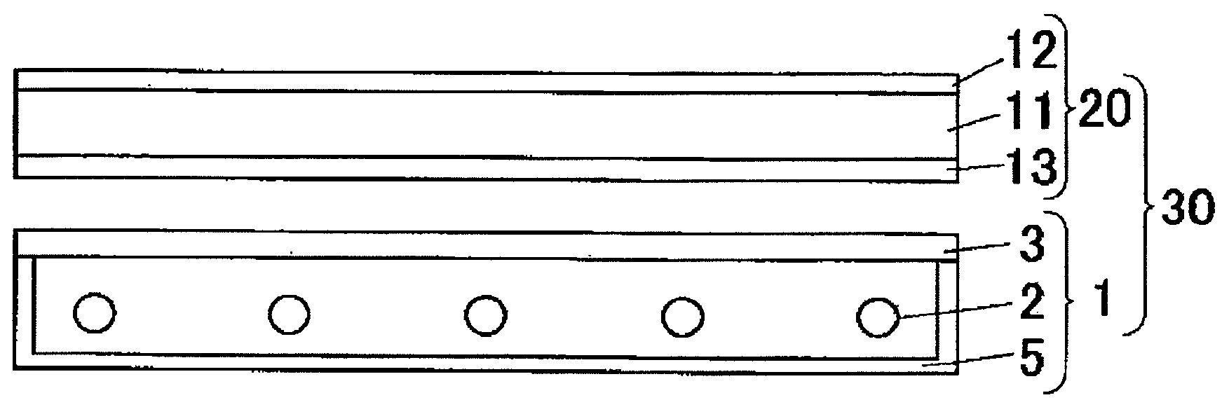
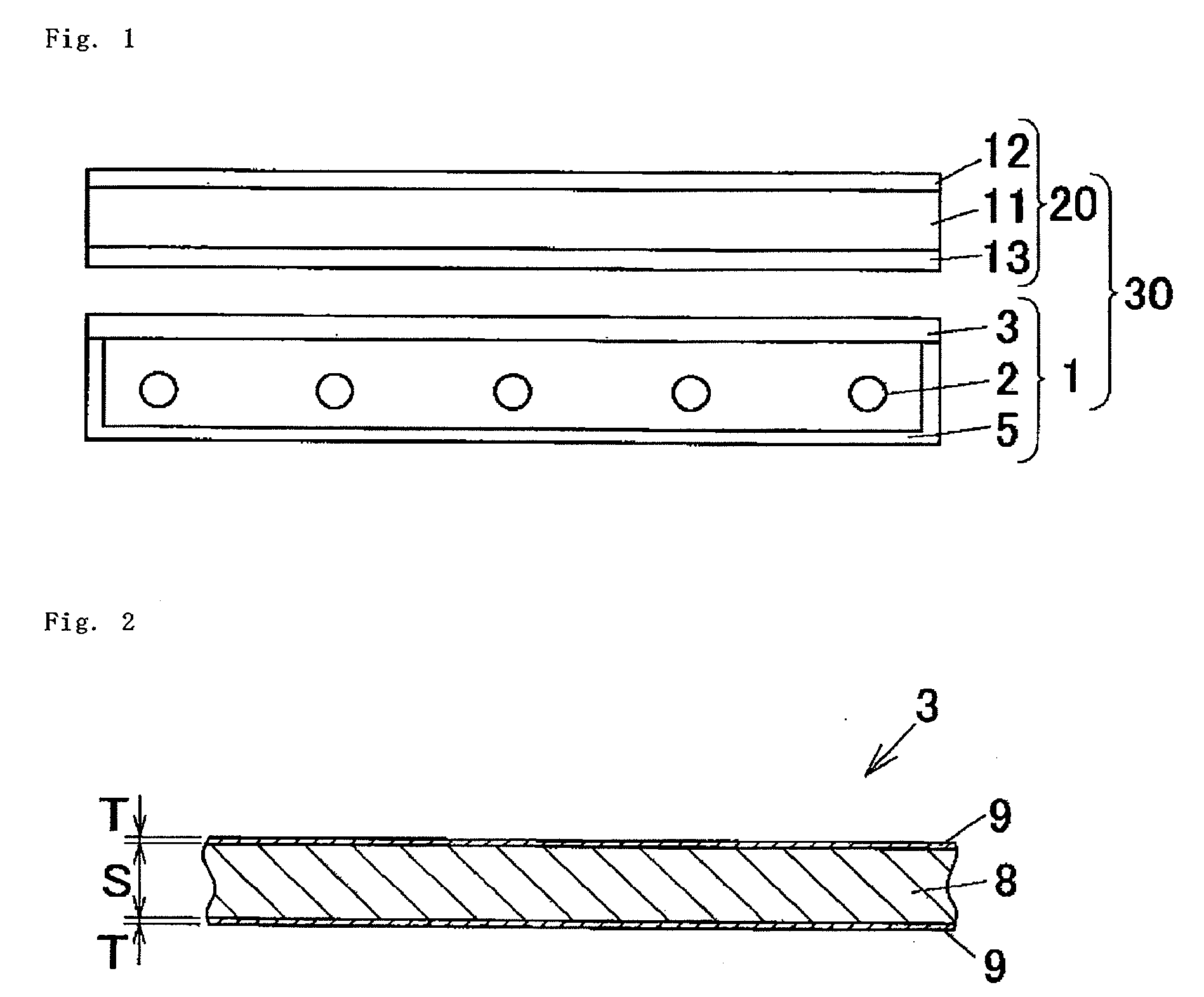
Image

Examples
example 1
[0066]Styrene-methacrylic acid copolymer pellets (“T080” manufactured by TOYO STYRENE CO., LTD.) (90 parts by mass) and the above-described master batch (pellets of light diffuser particles) (10 parts by mass) were dry-blended, and the resulting composition was supplied to a first extruder with a screw diameter of 40 mm and was melt-kneaded therein at 250° C. and was then supplied to a feed block.
[0067]On the other hand, a polycarbonate resin (“CALIBRE PC200-30” manufactured by SUMITOMO DOW LIMITED) (90.8 parts by mass), acrylic polymer particles (crosslinked polymer particles) (“SUMIPEX XC1A” with a volume-average particle size of about 25 μm, manufactured by Sumitomo Chemical Company, Limited) (8.0 parts by mass), Adekastab LA31 (a benzotriazole-based UV absorber manufactured by ADEKA) (1.0 part by mass) and Sumilizer GP (a processing stabilizer manufactured by Sumitomo Chemical Company, Limited) (0.2 parts by mass) were dry-blended, and the resulting composition was supplied to a...
example 2
[0069]A light diffuser plate was fabricated in the same manner as in Example 1, except that the thickness of the base layer was changed to 1.80 mm, and the thickness of the surface layer, to 100 μm.
example 3
[0070]A light diffuser plate was fabricated in the same manner as in Example 1, except that the thickness of the base layer was changed to 1.85 mm, and the thickness of the surface layer, to 75 μm.
PUM
| Property | Measurement | Unit |
|---|---|---|
| thickness | aaaaa | aaaaa |
| thickness | aaaaa | aaaaa |
| thickness | aaaaa | aaaaa |
Abstract
Description
Claims
Application Information
 - R&D
- Intellectual Property
- Life Sciences
- Materials
- Tech Scout
- Unparalleled Data Quality
- Higher Quality Content
- 60% Fewer Hallucinations
Browse by: Latest US Patents, China's latest patents, Technical Efficacy Thesaurus, Application Domain, Technology Topic, Popular Technical Reports.
© 2025 PatSnap. All rights reserved.Legal|Privacy policy|Modern Slavery Act Transparency Statement|Sitemap|About US| Contact US: help@patsnap.com