Ceramic element

a ceramic element and element technology, applied in the field of ceramic elements, can solve the problems of increasing the difficulty of meeting such demand using conventional methods, ineffectiveness, external electrode shorting, etc., and achieve the effect of preventing surface insulation resistance loss, and effectively controlling plating spread and plating adhesion

Active Publication Date: 2009-07-30
TDK CORPARATION
View PDF0 Cites 8 Cited by
  • Summary
  • Abstract
  • Description
  • Claims
  • Application Information

AI Technical Summary

Benefits of technology

[0010]The protective layer has the specific structure noted above and can thereby adequately prevent plating spread and plating adhesion during the plating process. Plating spread and plating adhesion are therefore controlled in the ceramic element of the present invention, and external electrode shorts are less likely to occur. The protective layer having the structure noted above is also less likely to become detached from the ceramic body and can therefore prevent a loss of surface insulation resistance in the ceramic element which may happen if the flux contained in the solder comes into contact with the ceramic body and reduces the ceramic body when the ceramic element is fixed and connected to a printed circuit board or the like by soldering the external electrode.
[0011]The protective layer preferably contains a silicon oxide as the insulating oxide. This will allow the protective layer to more effectively control plating spread and plating adhesion. The protective layer will eve

Problems solved by technology

However, the increasingly smaller sizes of recent ceramic elements have been accompanied by more and more demand for techniques to prevent external electrode shorts, and it is becoming more and more difficult to m

Method used


Image

  • Ceramic element
  • Ceramic element
  • Ceramic element

Examples


example 1

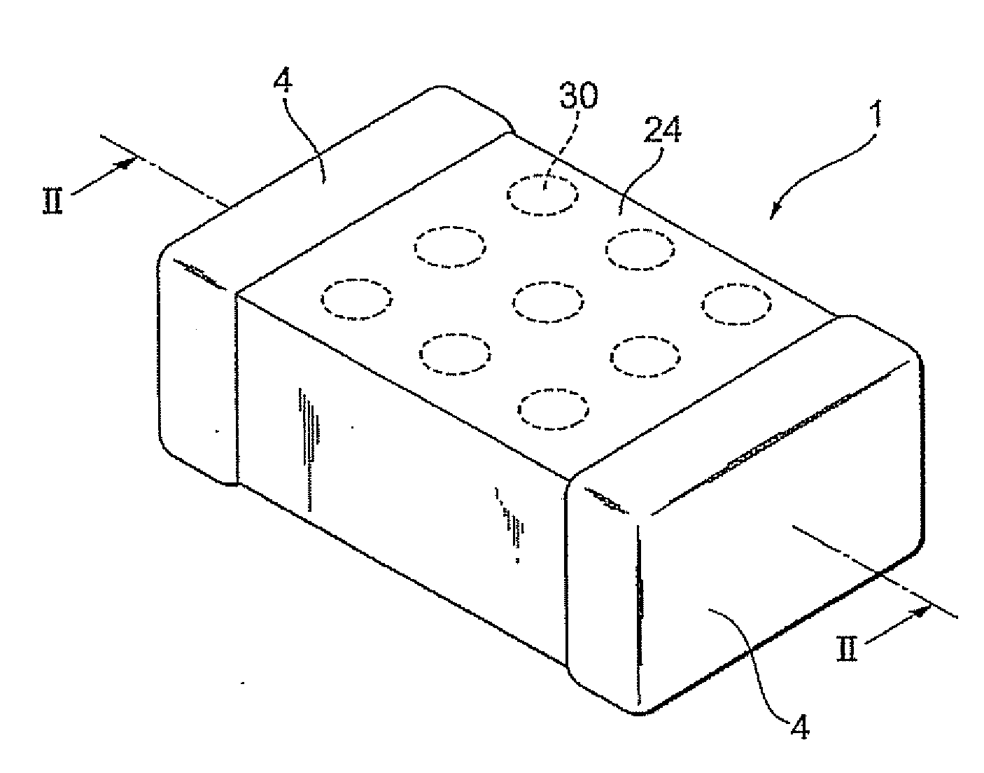
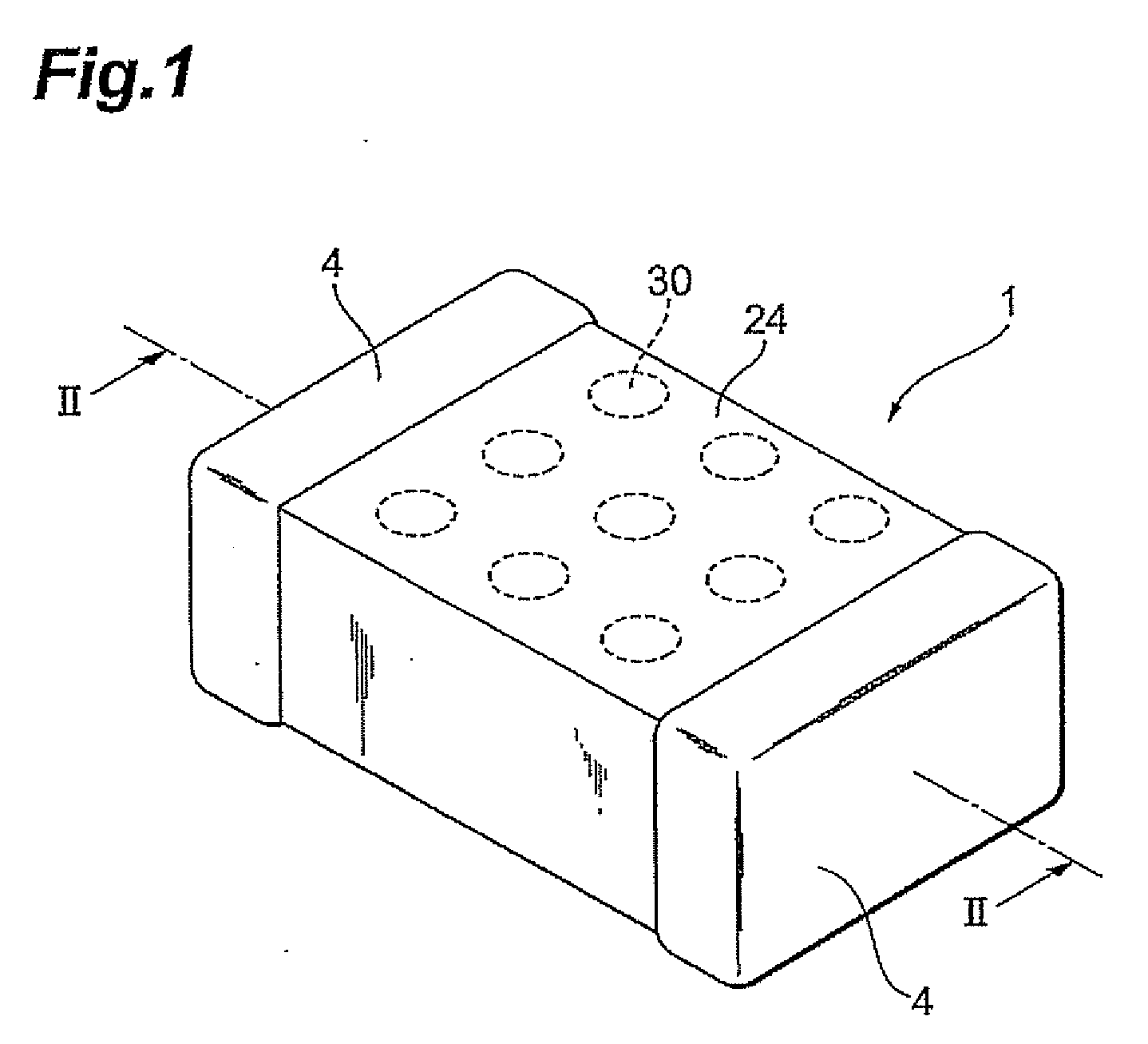
[0052]2000 of the resulting varistor bodies were introduced into a barrel (barrel diameter 200 mm and depth 200 mm) rotary RF sputtering equipment, and sputtering was carried out for a treatment time of 1.5 hours at 20 barrel rpm using SiO2 as the target, thereby forming a protective layer on the surfaces of the varistor bodies.

[0053]A metallic paste material containing silver (Ag) was applied to both opposing end faces of the varistor body on which the protective layer had been formed, and the paste was then baked at about 550 to 850° C., forming a base electrode. The outer surface of the base electrode was plated with nickel and then with stannum. This resulted in a varistor in which a protective layer, base electrode, and plating layers had been formed on the varistor body.

example 2

[0054]Varistors were obtained in the same manner as in Example 1 except that 25,000 varistor bodies were introduced into the barrel rotary RF sputtering equipment, and the treatment time was 5 hours.

[0055]Comparative Example 1

[0056]A protective layer based on SiO2 was formed by laser ablation on the surface of a varistor body. A varistor was then obtained by forming the base electrode and plating layers in the same manner as in Example 1.

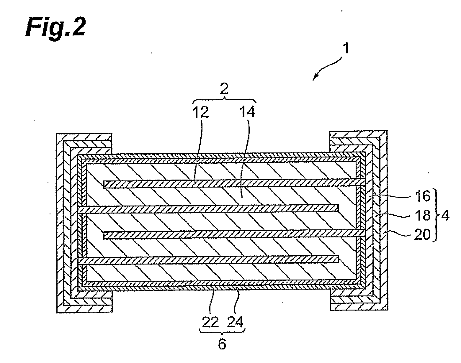
[0057]Investigation of Protective Layer

[0058]Analysis by STEM-EDS mapping of the structure of the protective layers in the varistors produced above revealed that two-layered structures composed of a first layer containing a silicon oxide and a second layer based on a silicon oxide and containing the element zinc had been formed in the examples. In the comparative example, on the other hand, a single-layered protective layer containing a silicon oxide was formed.

[0059]Plating Spread and Plating Adhesion

[0060]The appearance of the varistors obtained i...


PUM

PropertyMeasurementUnit
aaaaaaaaaa

Abstract

A ceramic element, including: a ceramic body having an internal electrode layer and a ceramic layer; an external electrode having a base electrode which is provided on the outside of the ceramic body so as to be electrically connected with the internal electrode layer, and a plating layer covering the outer surface of the base electrode; and a protective layer for covering at least a portion of the outer surface of the ceramic layer other than the portion covered by the external electrode, wherein the protective layer includes a first layer that is an insulating layer containing an insulating oxide, and a second layer that is an insulating layer containing the same insulating oxide as the first layer and an element that is the same as at least one of elements forming the ceramic layer, and the first layer and second layer are formed in that order from the inside.

Description

BACKGROUND OF THE INVENTION[0001]1. Field of the Invention[0002]The present invention relates to a ceramic element,[0003]2. Related Background Art[0004]Ceramic elements such as varistors, thermistors, and inductors are composed of a ceramic body having an internal electrode layer and ceramic layer, and an external electrode that is provided so as to be electrically connected to the internal electrode layer. Ceramic elements having the above structure are often fixed and connected by soldering the external electrode to a printed circuit board or the like. However, unmodified conventional external electrodes tend to melt from the solder heat and diffuse into the solder, which tends to result in poor connections. The solder heat resistance of external electrodes has conventionally been improved through a structure having a base electrode and a plating layer of Ni or the like formed on the surface thereof. In the interests of manufacturing costs and the like, such plating layers are gen...

Claims


Application Information

Patent Timeline
IPC IPC(8): B32B15/04
CPCH01C7/1006H01C7/18H01C7/102H01L27/02
Inventor NAKANO, MUTSUKOKOSEKI, KYOJIAIBA, HISASHIMURAKAMI, YUKIHIROTAKEYA, KAZUTO
Owner TDK CORPARATION
Why Eureka
Try Eureka