Electrode for electric storage device and electric storage device

a technology of electric storage device and electrode, which is applied in the direction of cell components, flat cell grouping, sustainable manufacturing/processing, etc., can solve the problems inability to suppress the temperature variation in the region, and the possibility of small cell active material being used for charging/discharging, etc., to suppress the temperature variation on the surface of the electrode, increase the area of the current collector, and suppress the effect of temperature variation

Active Publication Date: 2009-07-30
TOYOTA JIDOSHA KK
View PDF24 Cites 13 Cited by
  • Summary
  • Abstract
  • Description
  • Claims
  • Application Information

AI Technical Summary

Benefits of technology

[0026]According to the above aspects of the invention, the configuration of the electrode layer (more specifically, for example, the amount of the active material in the electrode layer) may vary such that the current density in the region of the electrode, where the heat radiation performance is lower than the heat radiation performance in the other region of the electrode, is lower than the current density in the other region of the electrode. This suppresses the variation in the temperature in the surface of the electrode.
[0027]Because the amount of the active material in the electrode layer varies, the variation in the temperature is suppressed. Therefore, the small electrode layers (electrode layers whose areas are small, i.e., small cells) need not be used, unlike the electrode described in the publication No. 2005-11660. That is, according to the above aspects of the invention, it is possible to increase the area of the current collector, on which the electrode layer is formed. Therefore, the energy efficiency of the electric storage device is improved, and separation of the electrode layer from the current collector is suppressed.

Problems solved by technology

However, the small cells are likely to separate from the current collector due to stress when the electrode for a secondary battery is bent.
Therefore, when the temperature varies in the region where each small cell is formed, it is not possible to suppress the variation in the temperature in the region.
That is, in the small cell that contains a small amount of the conductive agent, all the active material contained in the small cell may not be used for charging / discharging of the secondary battery.
The raw material of the active material is relatively expensive.
Therefore, if part of the active material is not used for charging / discharging of the secondary battery, the cost of the electrode for a secondary battery is increased.

Method used


Image

  • Electrode for electric storage device and electric storage device
  • Electrode for electric storage device and electric storage device
  • Electrode for electric storage device and electric storage device

Examples


first embodiment

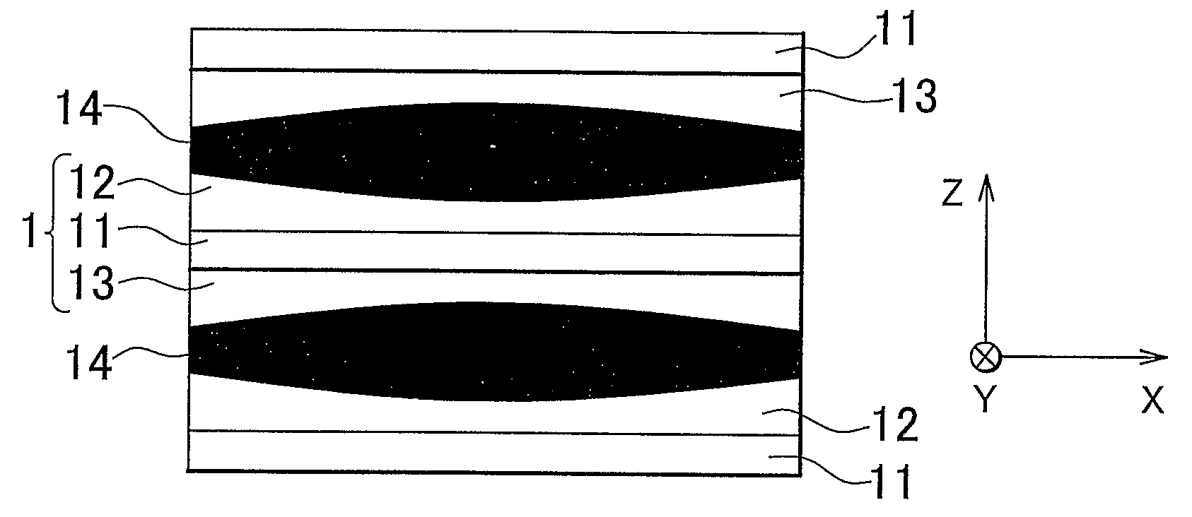
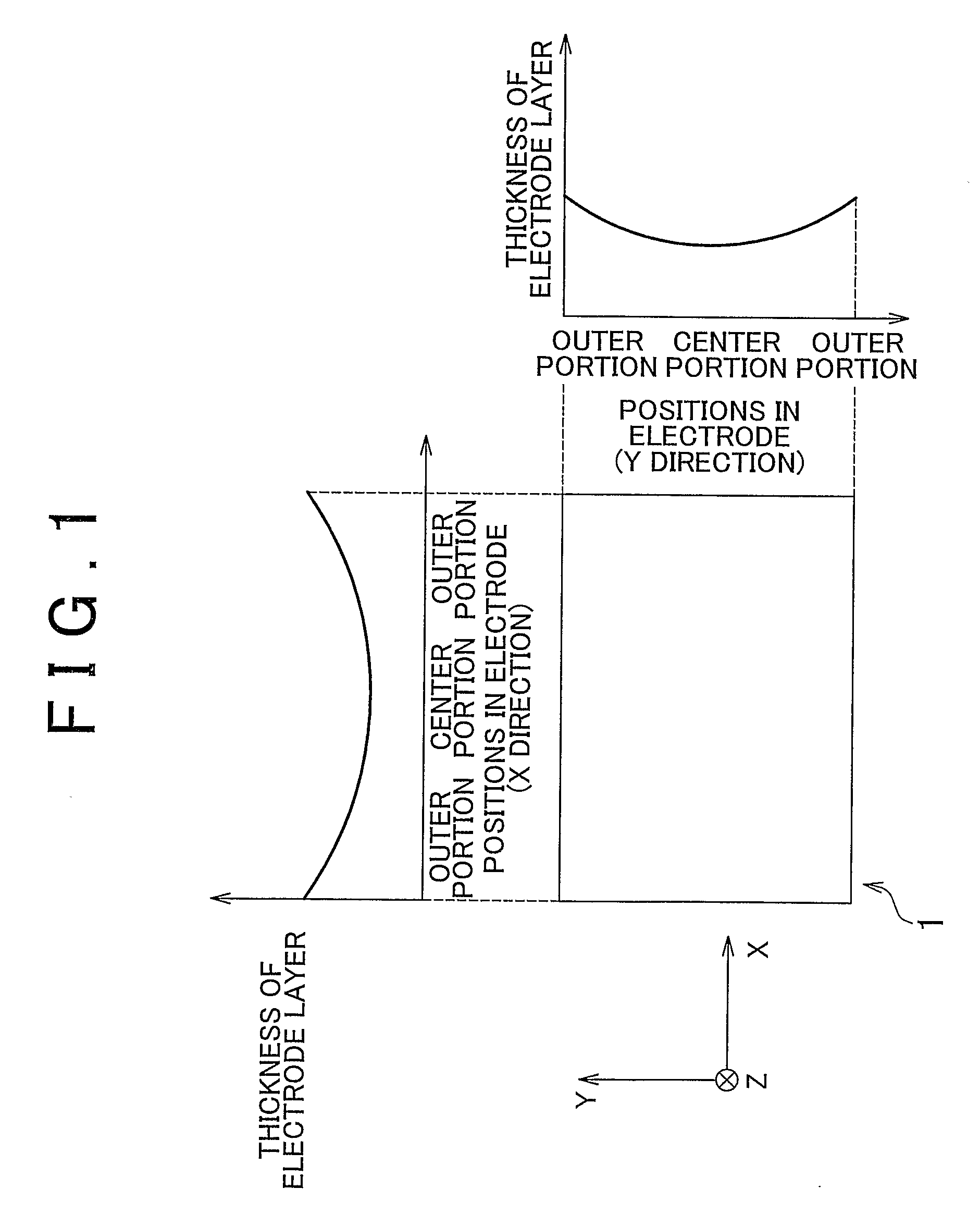
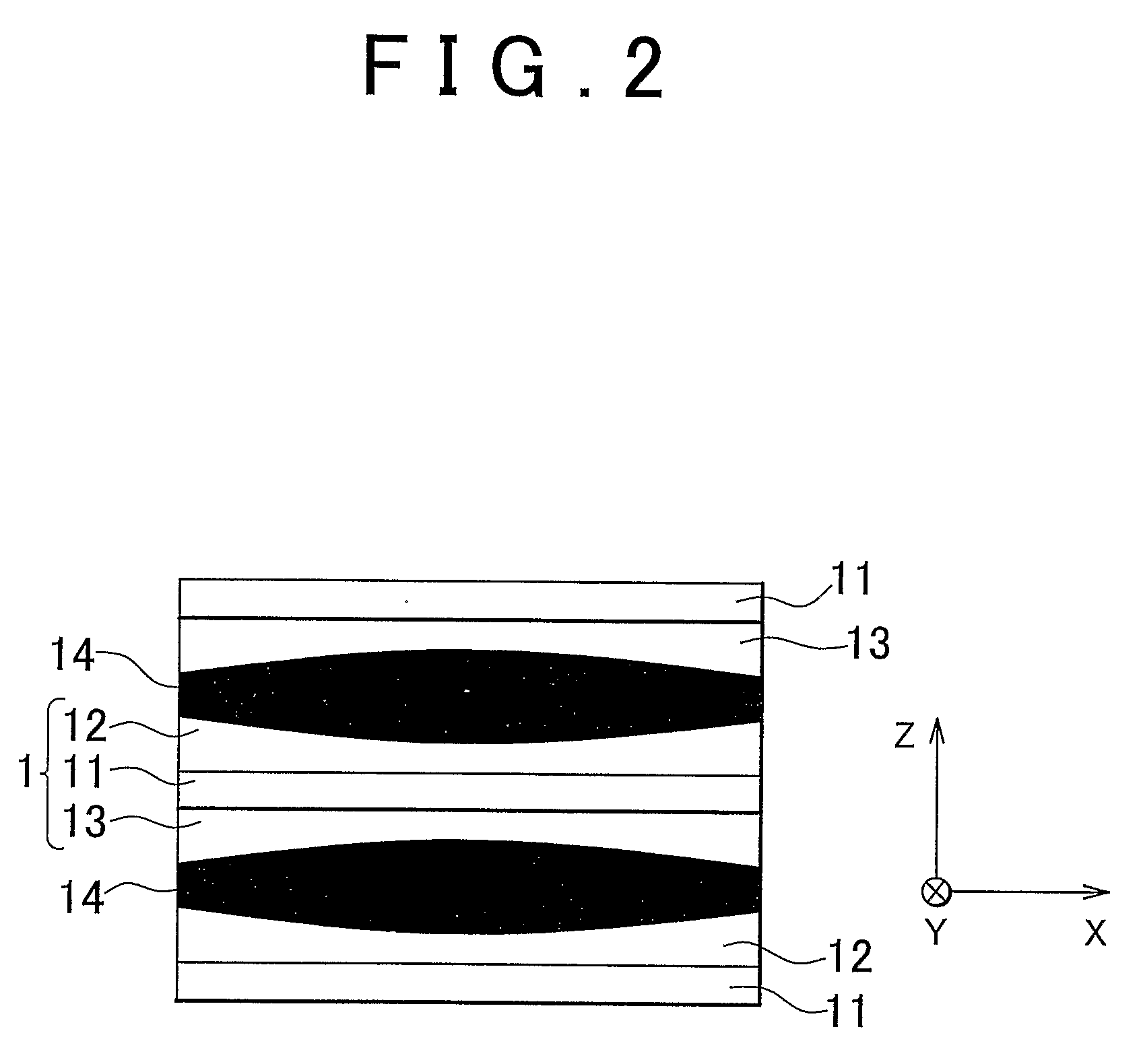
[0044]A bipolar battery, which is an electric storage device according to a first embodiment of the invention, will be described with reference to FIG. 1 and FIG. 2. FIG. 1 shows a front view of a bipolar electrode that is used in a bipolar battery according to the embodiment, and diagrams showing the relation between positions in the bipolar electrode, and the thickness of an electrode layer. FIG. 2 shows a lateral view of a portion of the bipolar battery that has a structure in which the bipolar electrodes are stacked.

[0045]In the bipolar electrode, a positive electrode layer is formed on one surface of a current collector, and a negative electrode layer is formed on the other surface of the current collector. FIG. 1 shows the one surface of the bipolar electrode (i.e., the surface on which the positive electrode layer is formed).

[0046]In the bipolar electrode according to the embodiment, the positive electrode layer and the negative electrode layer have the same configuration.

[00...

second embodiment

[0095]Next, a bipolar battery according to a second embodiment will be described with reference to FIG. 7 and FIG. 8. FIG. 7 shows a front view of a bipolar electrode used in the bipolar battery according to the second embodiment, and diagrams showing the relation between the density of the active material contained in the electrode layer in the bipolar electrode, and the positions in the bipolar electrode. FIG. 8 is a lateral view (schematic view) of the bipolar battery according to the embodiment.

[0096]In the above-described first embodiment, the thickness of the electrode layer varies in the X direction and Y direction of the bipolar electrode. In the second embodiment, the electrode layer has a substantially uniform thickness (when manufacturing tolerance is taken into account), and the density of the active material contained in the electrode layer varies. Hereinafter, more specific description will be made.

[0097]In a bipolar electrode 3 according to the embodiment, a positive ...


PUM

PropertyMeasurementUnit
ion-conductiveaaaaaaaaaa
current densityaaaaaaaaaa
thicknessaaaaaaaaaa

Abstract

An electrode is used for an electric storage device that includes plural electrodes that are stacked such that an ion-conductive layer is disposed between each pair of the electrodes. Each of the plural electrodes includes a current collector, and an electrode layer, formed on the current collector, which contains an active material. The configuration of the electrode layer (for example, the amount of the active material) varies according to the position in the electrode layer such that a current density in a first region of the electrode, where heat radiation performance is lower than the heat radiation performance in a second region of the electrode, is lower than the current density in the second region of the electrode.

Description

BACKGROUND OF THE INVENTION[0001]1. Field of the Invention[0002]The invention relates to an electrode for an electric storage device, which is used in an electric storage device such as a secondary battery or a capacitor, and an electric storage device that includes the electrode for an electric storage device.[0003]2. Description of the Related Art[0004]A secondary battery is widely used as a power source for a portable electronic device such as a laptop computer, or a cellular phone. The secondary battery is also used as a power source that provides power for an electric vehicle and the like. To suppress deterioration of the performance of the secondary battery, various proposals are made.[0005]Japanese Patent Application Publication No. 2005-11660 (JP-A-2005-11660) describes an electrode for a secondary battery. In the electrode for a secondary battery, plural small cells, which serve as electrode layers, are formed on a current collector, which serves as a substrate, to reduce t...

Claims


Application Information

Patent Timeline
Patent Type & Authority Applications(United States)
IPC IPC(8): H01M4/02H01G9/00H01G11/12H01G11/22H01G11/30H01G11/52H01G11/54H01G11/56H01G11/86H01M4/13H01M4/62H01M10/05H01M10/0562H01M10/0565H01M10/058H01M10/0585
CPCH01M4/13H01M4/24H01M4/364H01M4/621H01M4/624H01M10/0418Y02E60/124H01M10/345H01M10/5008H01M10/5032H01M10/5038H01M2004/021Y02E60/122H01M10/0525H01M10/617H01M10/647H01M10/652Y02E60/10Y02P70/50
Inventor NAKAMURA, YOSHIYUKI
Owner TOYOTA JIDOSHA KK
Why Eureka
Try Eureka