Method and system to facilitate combined cycle working fluid modification and combustion thereof

a technology of working fluid and combustion fluid, which is applied in the field of combustion systems, can solve the problems of increasing the complexity of the overall system, increasing the amount of waste generated by components within the system, and increasing the operational and maintenance costs of such systems, so as to facilitate the reduction of emissions generated within the gas turbine engine, and facilitate the displacing of nitrogen

Inactive Publication Date: 2009-08-06
GENERAL ELECTRIC CO
View PDF25 Cites 93 Cited by
  • Summary
  • Abstract
  • Description
  • Claims
  • Application Information

AI Technical Summary

Benefits of technology

[0004]In one aspect, a method of assembling a combustion system is provided. The method includes providing a gas turbine engine comprising a gas turbine section coupled downstream from a combustion chamber. The method further comprises coupling a source of oxygen to the gas turbine engine such that a stream of oxygen discharged from the source facilitates displacing nitrogen in the working fluid of the gas turbine engine and facilitates decreasing emissions generated within the gas turbine engine.
[0005]In another aspect, a combustion system is provided. The system includes a gas turbine engine and a source of oxygen coupled in flow communication with the gas turbine engine and configured to channel oxygen to the gas turbine engine to facilitate displacing nitrogen in combustion gases channeled to the gas turbine engine and to facilitate reducing emissions generated within the gas turbine engine.

Problems solved by technology

However, the presence of nitrogen in the combustion process may contribute to the production of harmful emissions, including nitrogen oxide (NOx).
However, the additional component needed to provide the purified stream of fluid increases the complexity of the overall system, and increases the amount of waste generated by components within the system.
As such, the operational and maintenance costs of such systems are increased by such components and the overall efficiency of the system may be decreased.

Method used


Image

  • Method and system to facilitate combined cycle working fluid modification and combustion thereof
  • Method and system to facilitate combined cycle working fluid modification and combustion thereof
  • Method and system to facilitate combined cycle working fluid modification and combustion thereof

Examples


Embodiment Construction

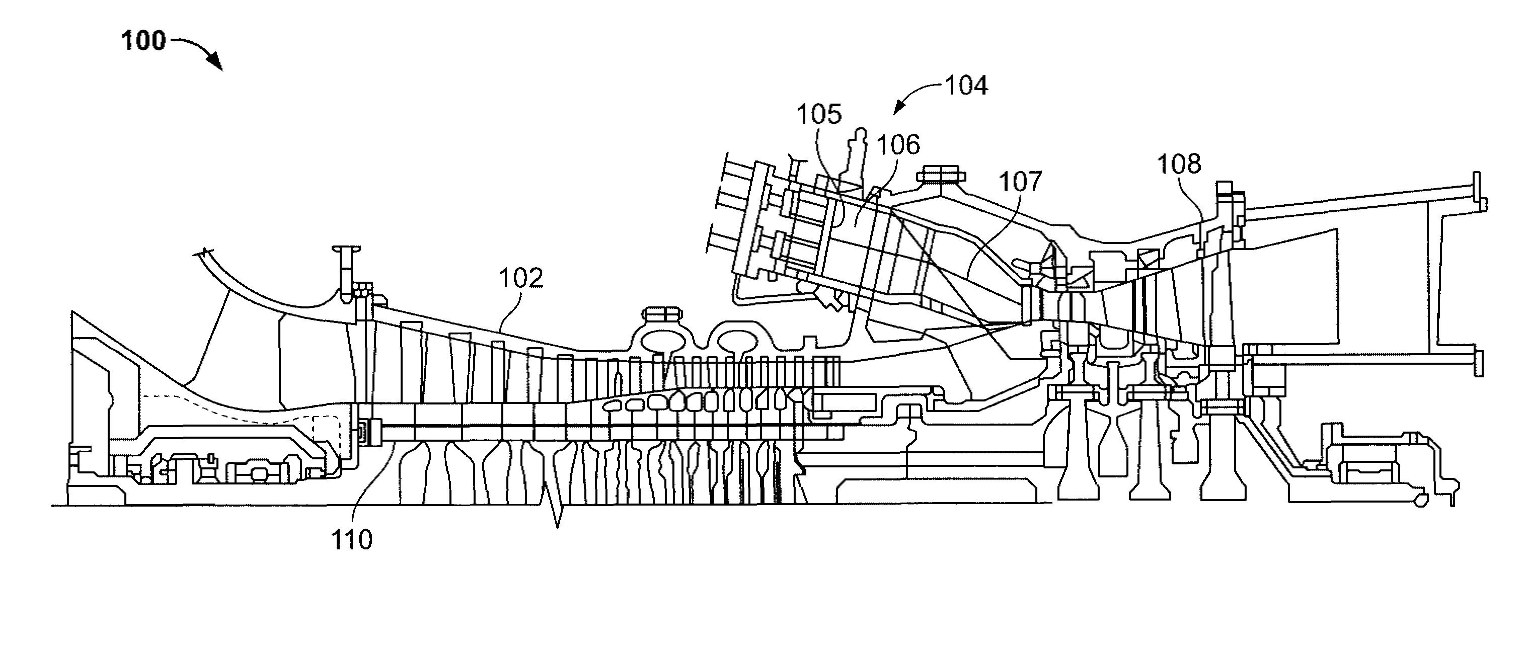
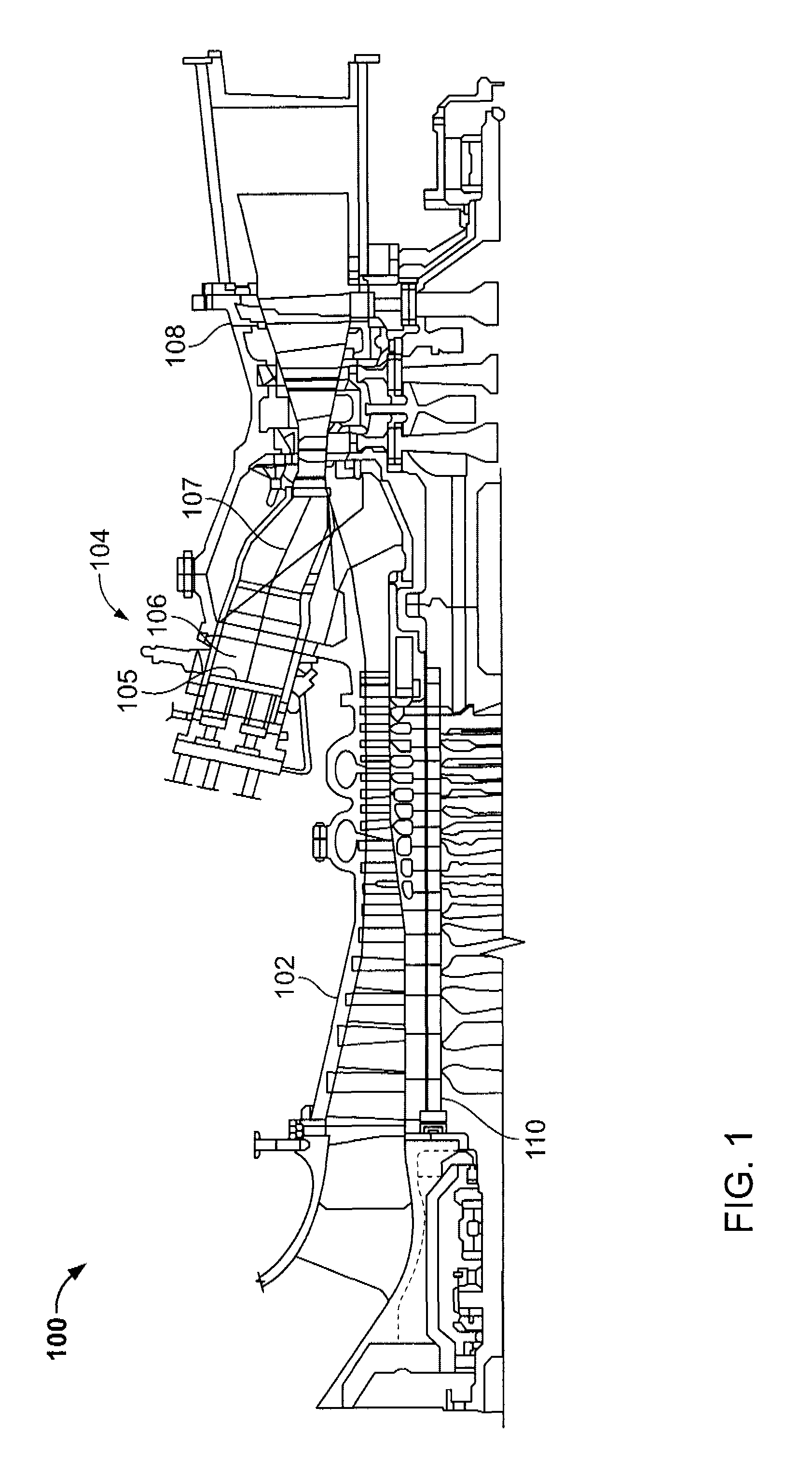
[0009]FIG. 1 is a schematic illustration of an exemplary gas turbine engine 100. In the exemplary embodiment, engine 100 includes a compressor 102 and a combustor assembly 104. Combustor assembly 104 includes a combustor assembly head 105 providing fuel into combustion chamber 106 that includes a centerline 107 that extends therethrough. In the exemplary embodiment, engine 100 includes a plurality of combustor assemblies 104. Combustor assembly 104, and, more specifically, combustion chambers 106 are coupled downstream from, and in flow communication with, compressor 102. Engine 100 also includes a gas turbine engine section 108 and a compressor / turbine shaft 110 (sometimes referred to as a rotor). In the exemplary embodiment, combustion chamber 106 is substantially cylindrical and is coupled in flow communication with gas turbine engine section 108. Turbine 108 is mechanically coupled to, and drives, shaft 110. Compressor 102 is also rotatably coupled to shaft 110. In the exemplary...


PUM

PropertyMeasurementUnit
temperatureaaaaaaaaaa
thermal energyaaaaaaaaaa
mechanical rotational energyaaaaaaaaaa

Abstract

A method of assembling a combustion system includes providing a gas turbine engine that includes a gas turbine section coupled downstream from a combustion chamber and coupling a source of oxygen to the gas turbine engine such that a stream of oxygen discharged from the source facilitates displacing nitrogen in the working fluid of the gas turbine engine and facilitates decreasing emissions generated within the gas turbine engine.

Description

BACKGROUND OF THE INVENTION[0001]The present invention relates generally to combustion systems, and more particularly, to methods and systems that provide a stream of oxygen enriched fluid and a stream of nitrogen enriched fluid for use in a gas turbine engine.[0002]At least some known industrial facilities include combustion systems that operate by combusting a stream of inlet air with a stream of fuel to produce an exhaust stream. At least some of the known combustion systems include a heat recovery steam generator that uses exhaust gases discharged from a gas turbine engine to produce an amount of steam. The steam is channeled through a steam turbine for the production of power. Known combustion systems may also include heat exchangers, flow control valves, and generators. Moreover, at least some known systems also include an air compressor that provides a compressed stream of inlet fluid to the gas turbine engine.[0003]At least some known gas turbine engines include a compressor...

Claims


Application Information

Patent Timeline
Patent Type & Authority Applications(United States)
IPC IPC(8): F02C3/22B23P11/00F02C6/00
CPCF02C3/22Y10T29/53Y02E20/16F02C6/18
Inventor SCHRODER, MARK STEWARTHADLEY, MARK ALLANDEPUY, RICHARD ANTHONYNEMEC, TODD STANLEY
Owner GENERAL ELECTRIC CO
Why Eureka
Try Eureka