Co2 recovery system and method of cleaning filtration membrane apparatus

a filtration membrane and co2 recovery technology, applied in the direction of liquid degasification, membranes, separation processes, etc., can solve the problems of water thereby not being discharged, the loss of co2 absorbent solution b>1005/b> increases, and the value of co2 in the wastewater is high

Active Publication Date: 2009-08-06
MITSUBISHI HEAVY IND ENG LTD
View PDF20 Cites 36 Cited by
  • Summary
  • Abstract
  • Description
  • Claims
  • Application Information

AI Technical Summary

Problems solved by technology

However, because the CO2-absorbing solution is attached to the filter, if the filter or the filtering material is discarded as it is upon replacement thereof, the loss of the CO2-absorbing solution 1005 increases.
Because of this, a chemical oxygen demand (COD) value in the wastewater is high and the water cannot thereby be discharged to the outside of the system as it is as wastewater.

Method used


Image

  • Co2 recovery system and method of cleaning filtration membrane apparatus
  • Co2 recovery system and method of cleaning filtration membrane apparatus
  • Co2 recovery system and method of cleaning filtration membrane apparatus

Examples


first embodiment

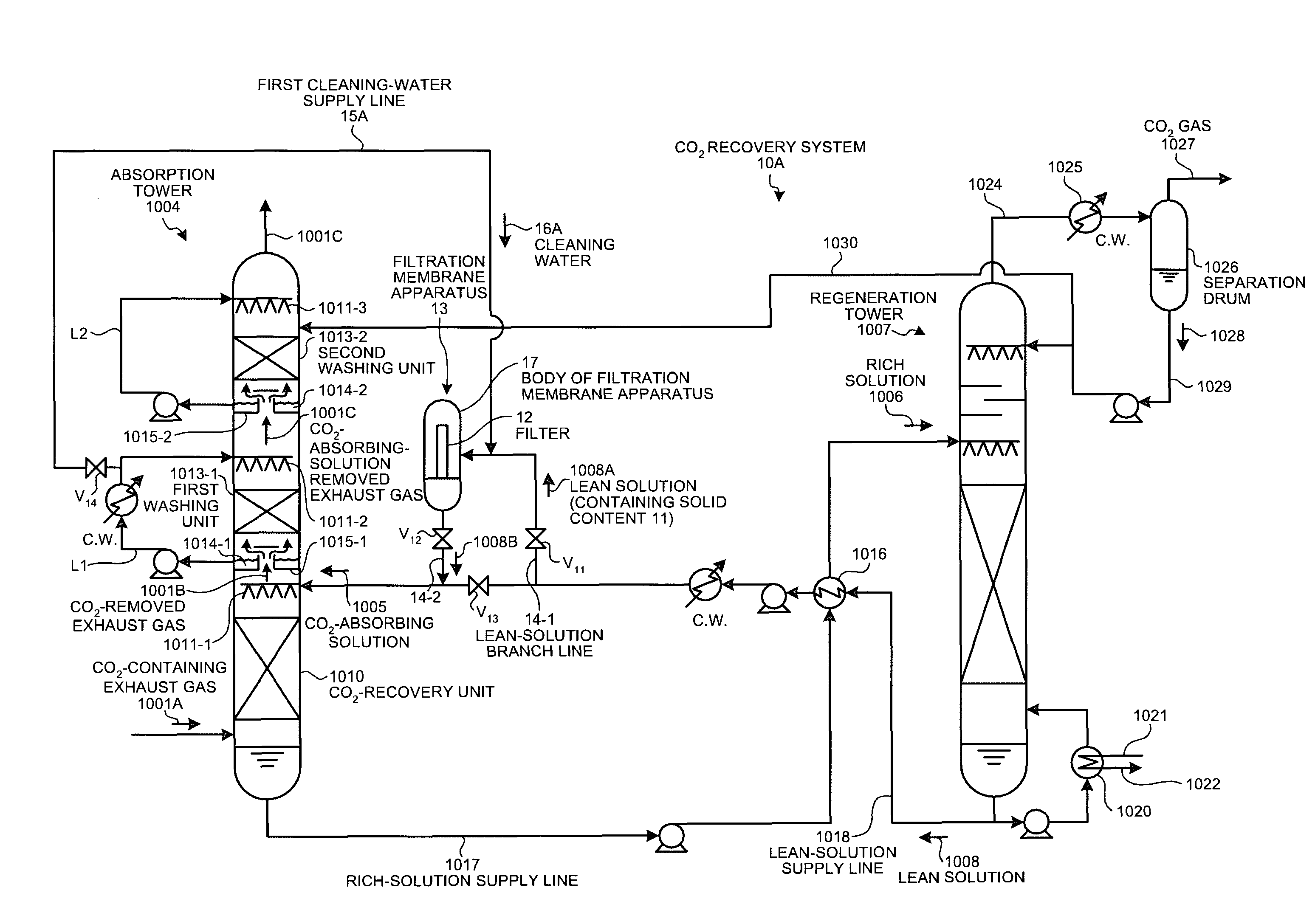
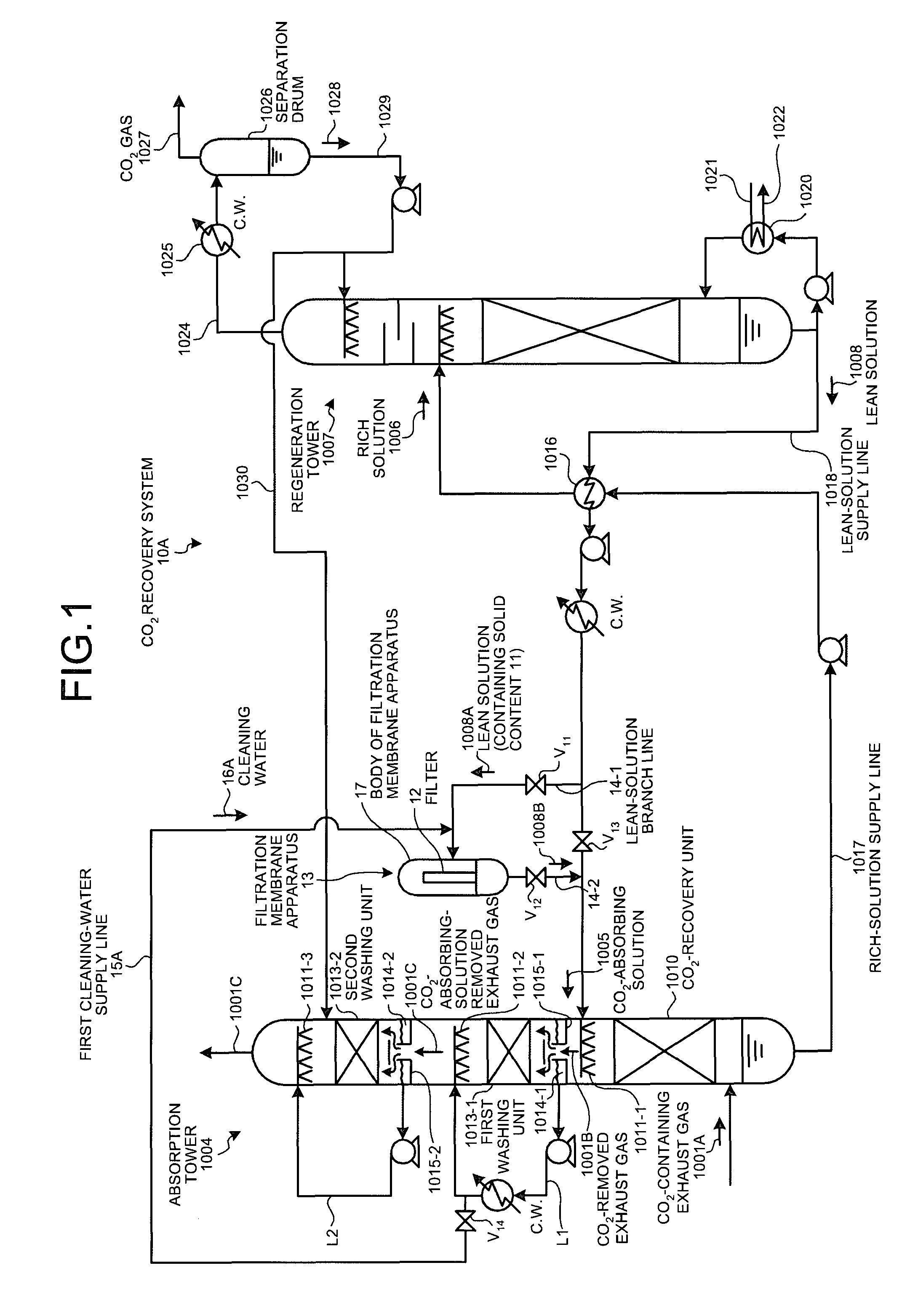
[0041]FIG. 1 is a schematic of a CO2 recovery system 10A according to the present invention. In FIG. 1, the same reference numerals are assigned to the same components as these of the CO2 recovery system shown in FIG. 8, and explanation thereof is omitted. It is noted that the drawing of the cooling tower 1002 shown in FIG. 8 is omitted.

[0042]As shown in FIG. 1, the CO2 recovery system 10A includes the absorption tower 1004 that causes the CO2-containing exhaust gas 1001A to come in contact with the CO2-absorbing solution 1005 and removes CO2, the regeneration tower 1007 that regenerates the rich solution 1006 having absorbed CO2 by heat exchange, and the separation drum 1026 that condenses steam in CO2 gas with the stream released from the regeneration tower 1007 and separates water therefrom. The CO2 recovery system 10A reuses the lean solution (regenerated solution) 1008 in the absorption tower 1004, the lean solution 100 being produced by removing CO2 from the rich solution in t...

second embodiment

[0070]A CO2 recovery system according to the present invention will be explained below with reference to FIG. 3.

[0071]FIG. 3 is a schematic of a CO2 recovery system 10B according to the second embodiment. In FIG. 3, the same reference numerals are assigned to the same components as these of the CO2 recovery system 10A shown in FIG. 1, and explanation thereof is omitted. It is noted that the drawing of the cooling tower 1002 is omitted.

[0072]As shown in FIG. 3, the CO2 recovery system 10B uses the condensed water 1014-2, as cleaning water, circulating in the second circulation line L2 instead of the condensed water 1014-1 in the CO2 recovery system 10A.

[0073]More specifically, the CO2 recovery system 10B includes a second cleaning-water supply line 15B that supplies the condensed water 1014-2 collected by the second condensed-water receiver 1015-2 to the lean-solution branch line 14-1 through the second circulation line L2, instead of the first cleaning-water supply line 15A in the C...

third embodiment

[0080]A CO2 recovery system according to the present invention will be explained below with reference to FIG. 4.

[0081]FIG. 4 is a schematic of a CO2 recovery system 10C according to the third embodiment. In FIG. 4, the same reference numerals are assigned to the same components as these of the CO2 recovery system 10A shown in FIG. 1, and explanation thereof is omitted. It is noted that the drawing of the cooling tower 1002 is omitted.

[0082]As shown in FIG. 4, the CO2 recovery system 10C uses the water 1028 being cleaning water that is discharged from the regeneration tower 1007 and is separated by the separation drum 1026, instead of the condensed water 1014-1 used in the CO2 recovery system 10A.

[0083]More specifically, the CO2 recovery system 10C includes a third cleaning-water supply line 15C that supplies the separated water 1028 to the lean-solution branch line 14-1, instead of the first cleaning-water supply line 15A in the CO2 recovery system 10A.

[0084]By providing the third c...


PUM

PropertyMeasurementUnit
wt. %aaaaaaaaaa
wt. %aaaaaaaaaa
wt. %aaaaaaaaaa

Abstract

A CO2 recovery system includes an absorption tower that removes CO2 from exhaust gas, a regeneration tower that regenerates a rich solution, and a separation drum that condensates steam in CO2 gas released from the regeneration tower and separates water. The CO2 recovery system further includes a filtration membrane apparatus that filters solid content remaining in the lean solution using a filter, and cleans the filter using condensed water as cleaning water and again return the condensed water into the system. The CO2-absorbing solution attached to the filter is collected and the filter is cleaned without diluting the CO2-absorbing solution upon replacement of the filter.

Description

BACKGROUND OF THE INVENTION[0001]1. Field of the Invention[0002]The present invention relates to a technology for replacing a filter that collects soot and solid content by filtering a CO2-absorbing solution used to remove CO2 or the like from exhaust gas, and for cleaning a filtration membrane apparatus.[0003]2. Description of the Related Art[0004]In recent years the greenhouse effect due to CO2 has been pointed out as one of causes of the global warming, and a countermeasure against it is urgently required internationally to protect global environment. CO2 sources range various fields of human activities, including burning of fossil fuels, and demands to suppress their CO2 emission from these sources are on constant increase. In association with this, people have energetically studied methods for suppressing CO2 from power generation facilities such as power plants which use an enormous amount of fossil fuels. One of the methods includes bringing combustion exhaust gas of boilers ...

Claims


Application Information

Patent Timeline
Patent Type & Authority Applications(United States)
IPC IPC(8): B01D53/62B01D53/78C01B32/50
CPCB01D53/1406B01D53/1425B01D61/14B01D61/147B01D65/02B01D2257/504B01D2311/04Y02C10/06B01D2321/08B01D2321/185Y02C10/04B01D2311/2626Y02C20/40
Inventor IIJIMA, MASAKI
Owner MITSUBISHI HEAVY IND ENG LTD
Why Eureka
Try Eureka