
Plasma Generating Ignition System and Associated Method

Active Publication Date: 2009-08-06
WEST VIRGINIA UNIVERSITY
View PDF7 Cites 27 Cited by
  • Summary
  • Abstract
  • Description
  • Claims
  • Application Information

AI Technical Summary

Benefits of technology

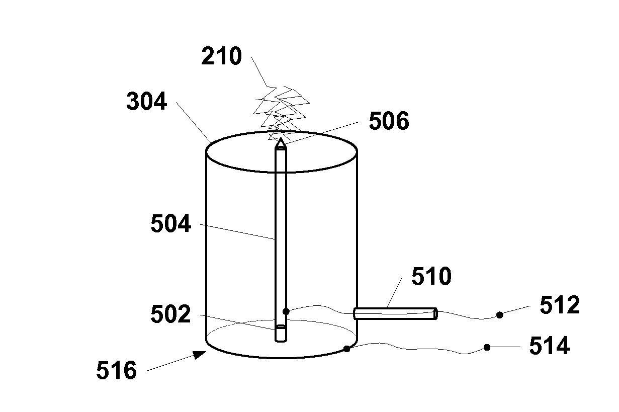
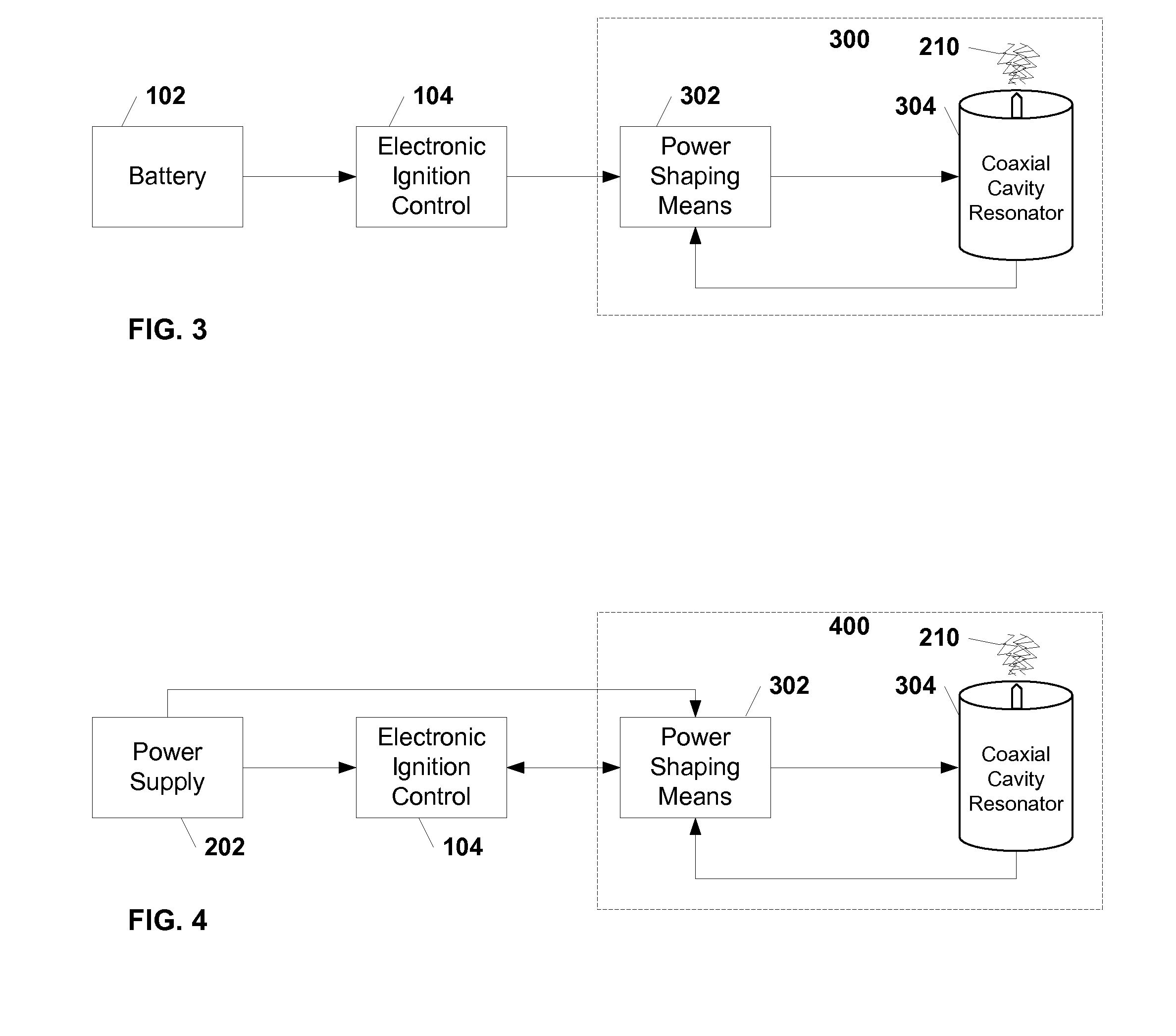
[0006]The present invention meets the above and other needs. An apparatus that uses the coaxial cavity resonator as the frequency determining element in producing radio frequency (RF) energy comprises a coaxial cavity resonator operably coupled with an energy shaping means such that a sustained RF oscillation is generated closer to or at the resonant frequency of the coaxial cavity resonator for optimal corona discharge plasma generation. The apparatus can have a body adapted t

Problems solved by technology

However, the cavity still generates a corona discharge plasma for a range of frequencies around the optimal frequency as well as at higher harmonics of the optimal frequency, although the unmatched coaxial cavity resonator generally results in lower efficiencies and less power being delivered to the coaxial cavity resonator and therefore potentially less corona discharge plasma.
When the corona discharge plasma is used as an ignition source for a combustion chamber, a reduction in the amount or strength of the corona discharge plasma is undesirable as it could result in non-ignition of combustible materials in the combustion chamber.
However, in practice, the resonant frequency of a coaxial cavity resonator may not be optimally matched with the RF oscillator and amplifier.
This can occur for any number of reasons, including improper selection of frequency in the RF oscillator, mechanical fatigue and wearing of the coaxial cavity resonator or dielectric, or even transient changes in the resonant frequency of the coaxial cavity resonator due to, for example, the formation of the corona discharge plasma itself or other changes in the environment near the region of the cavity.

Method used


Image

  • Plasma Generating Ignition System and Associated Method
  • Plasma Generating Ignition System and Associated Method
  • Plasma Generating Ignition System and Associated Method

Examples


Embodiment Construction

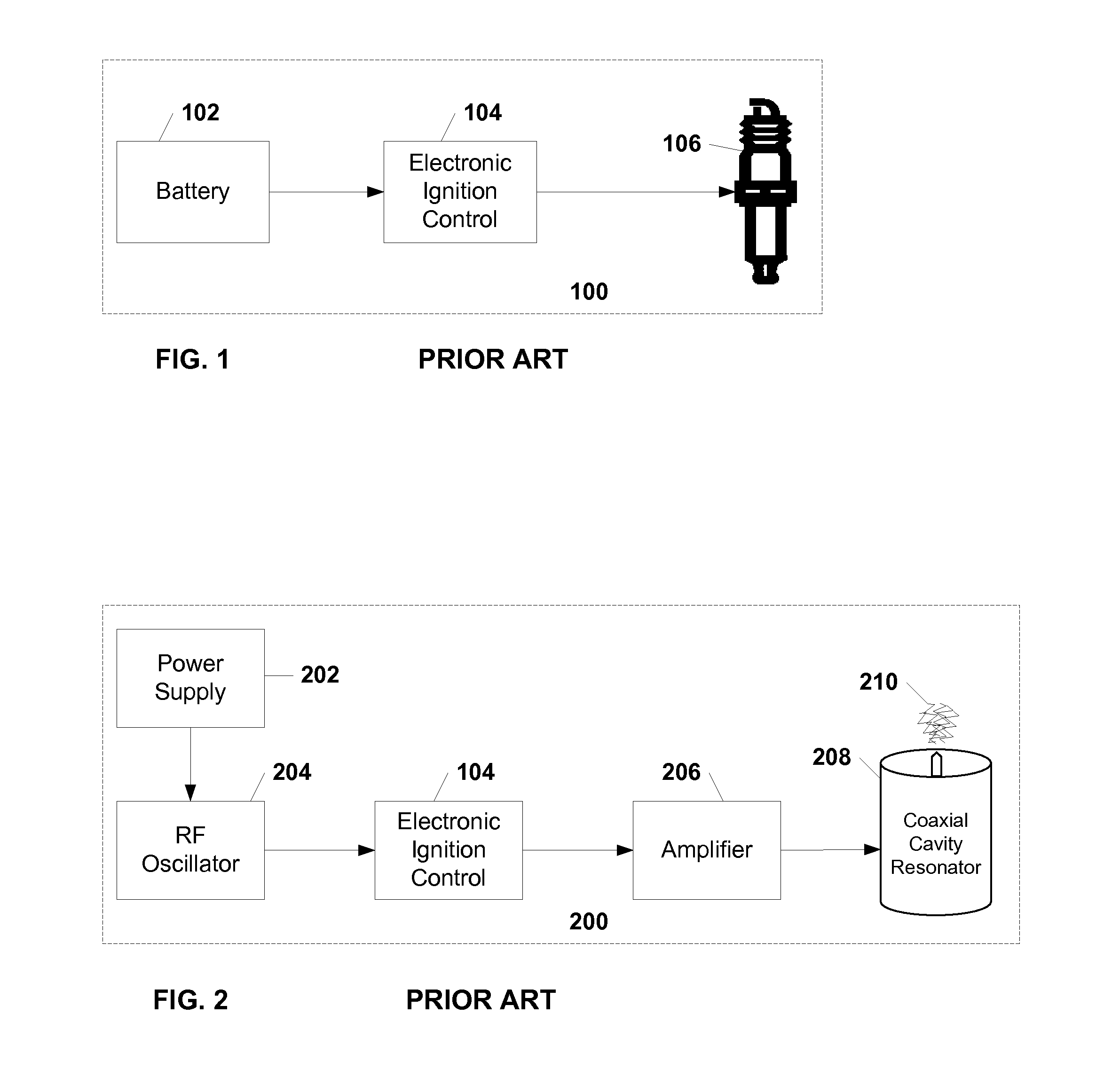
[0023]FIG. 1 and FIG. 2 detail the prior art ignition systems. Exemplary embodiments of the present invention are detailed in FIGS. 3-14.

Prior Art Ignition System with a Spark Plug

[0024]Referring now to the schematic diagram of a prior art ignition system 100 depicted in FIG. 1, a battery 102 connects to an electronic ignition control system 104 which is connected by a spark plug wire to the terminal end of a spark plug 106.

[0025]In a typical prior art ignition system 100, like that found in an automobile, a battery 102 provides electrical power to an electronic ignition control system 104. The electronic ignition control system 104 determines the proper timing for triggering an ignition event, and at the appropriate time sends a high voltage pulse via a spark plug wire to the terminal end of a spark plug 106. The high voltage pulse causes a spark to discharge at the tip of the spark plug 106 that is displaced inside of a combustion chamber (not shown). The spark ignites combustible...


PUM


Abstract

An apparatus and method for igniting combustible materials in a combustion chamber of a combustion engine using corona discharge plasma from a coaxial cavity resonator. This system and method uses a coaxial cavity resonator in a body adapted to mate with a combustion chamber of a combustion engine. The coaxial cavity resonator is coupled with an energy shaping means that develops the appropriate waveform for triggering radio frequency oscillations in the coaxial cavity resonator. A connection means on the apparatus allows for the apparatus to accept an electrical ignition stimulus from an electronic ignition control system. The coaxial cavity resonator develops corona discharge plasma at a discharge electrode when a sustained radio frequency oscillation results in a standing wave in the coaxial cavity resonator. The corona discharge plasma developed near the discharge electrode ignites the combustible materials in the combustion chamber of the combustion engine.

Description

TECHNICAL FIELD[0001]The present invention relates generally to systems, devices, and methods for using a coaxial cavity resonator in producing radio frequency (RF) energy for generating a corona discharge plasma, and using the corona discharge plasma as an ignition means in combustion engines and processes.BACKGROUND OF THE INVENTION[0002]Prior art methods and apparatuses describe using plasma as an ignition means for combustion engines. One method of generating plasma involves using a radio frequency (RF) source and a coaxial cavity resonator to generate corona discharge plasma. The prior art uses a radio frequency (RF) oscillator and amplifier to generate the required RF power at a desired frequency. RF oscillators and amplifiers can be either semiconductor or electron tube based, and are well known in the art. The RF oscillator and amplifier are coupled to the coaxial cavity resonator, which in turn develops a standing RF wave in the cavity at the frequency determined by the RF ...

Claims


Application Information

Patent Timeline
IPC IPC(8): F02B23/00
CPCF02P23/045F02P9/007F02P3/01
Inventor SMITH, JAMES E.PERTL, FRANZ A.
Owner WEST VIRGINIA UNIVERSITY
Learn More