[0017]In view of the foregoing, embodiments of the present invention provide systems, program products, and methods to enhance the controlling of drilling fluid pressures and other parameters such as in an oil or gas well. Embodiments of systems, program products, and methods for controlling drilling pressures of the present invention, for example, advantageously provide dynamic density control (DDC) and dynamic
mud weight windows (DMWW). These embodiments having DDC provide highly adaptive, real-time,
process control and can be scalable to any rig, large or small, on land or water. Embodiments of systems, program products, and methods also advantageously allow combined static and dynamic stresses and displacements to be determined continuously at strategic locations in and around the
wellbore so that insitu and operationally induced pressure window limitations at specific weal-points are controlled. By
coupling feedback loops and high-rate, high-quality, time-lapse data
logging, for example, embodiments of the present invention allow an operator /
service company team to “walk-the-line” or even “move-the-line”.
[0018]For example,
mass and energy balances for an active
system account for time-varying bulk volumes, stresses, pressures, fluids, and temperatures, coupled and associated with flows, displacement or movement. On or off switching circuitry can activate individual
system element quantifiers in isolation or coupled with other elements to allow selected usage, maximum usage, or no usage of the enhanced system features. An embodiment of a method of controlling drilling fluid pressures includes monitoring the
fluid pressure in real-time and increasing fluid head pressure within a
drill pipe and annulus of a well to thereby control downhole pressures within pre-selected limits.
[0019]Additionally, many applications for embodiments of systems, program products, and methods of the present invention abound. For example, applications can include detecting pressure changes where critical pressure magnitudes and small pressure tolerances have large economic, technical, safety, and environmental consequences; in distinguishing between kicking flow and ballooning flow in kick / loss scenarios; in minimizing formation damage during drilling / completion operations; in identifying likely trouble spots in advance; and in training, predictive, what-ifs, and case studies.
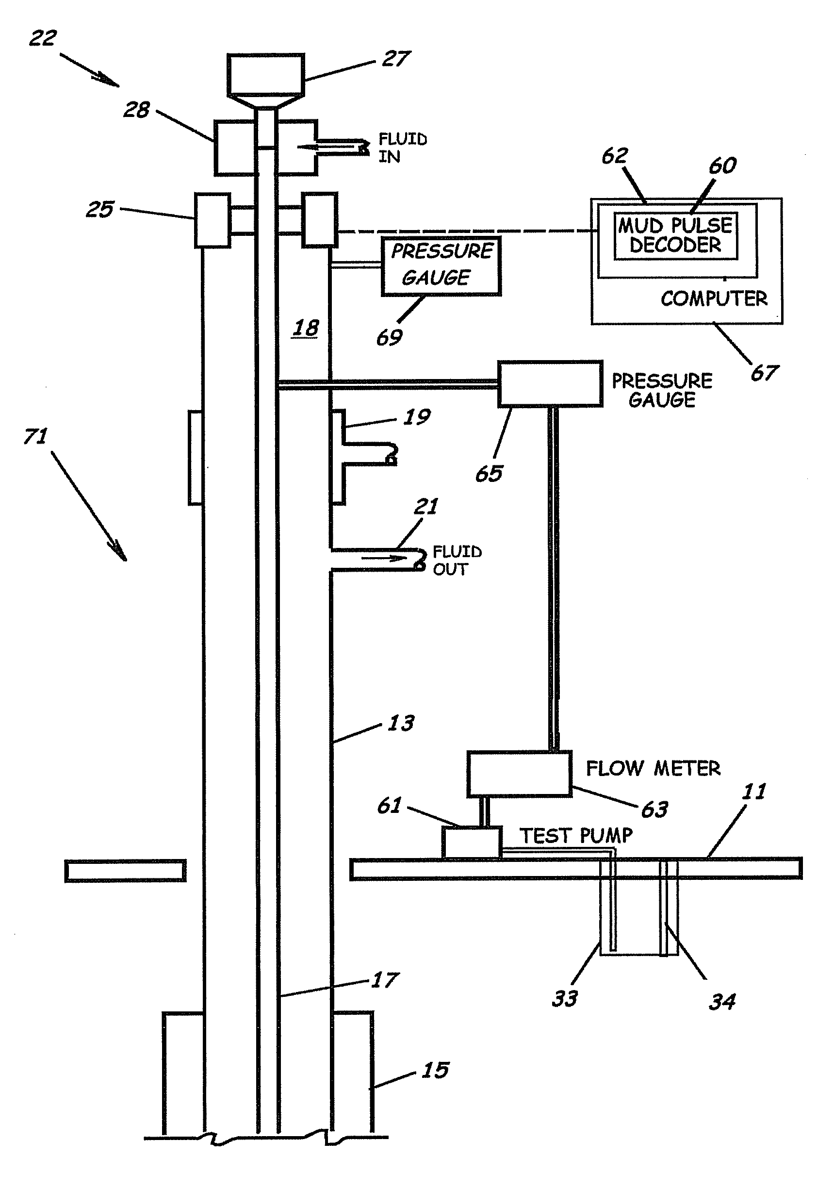
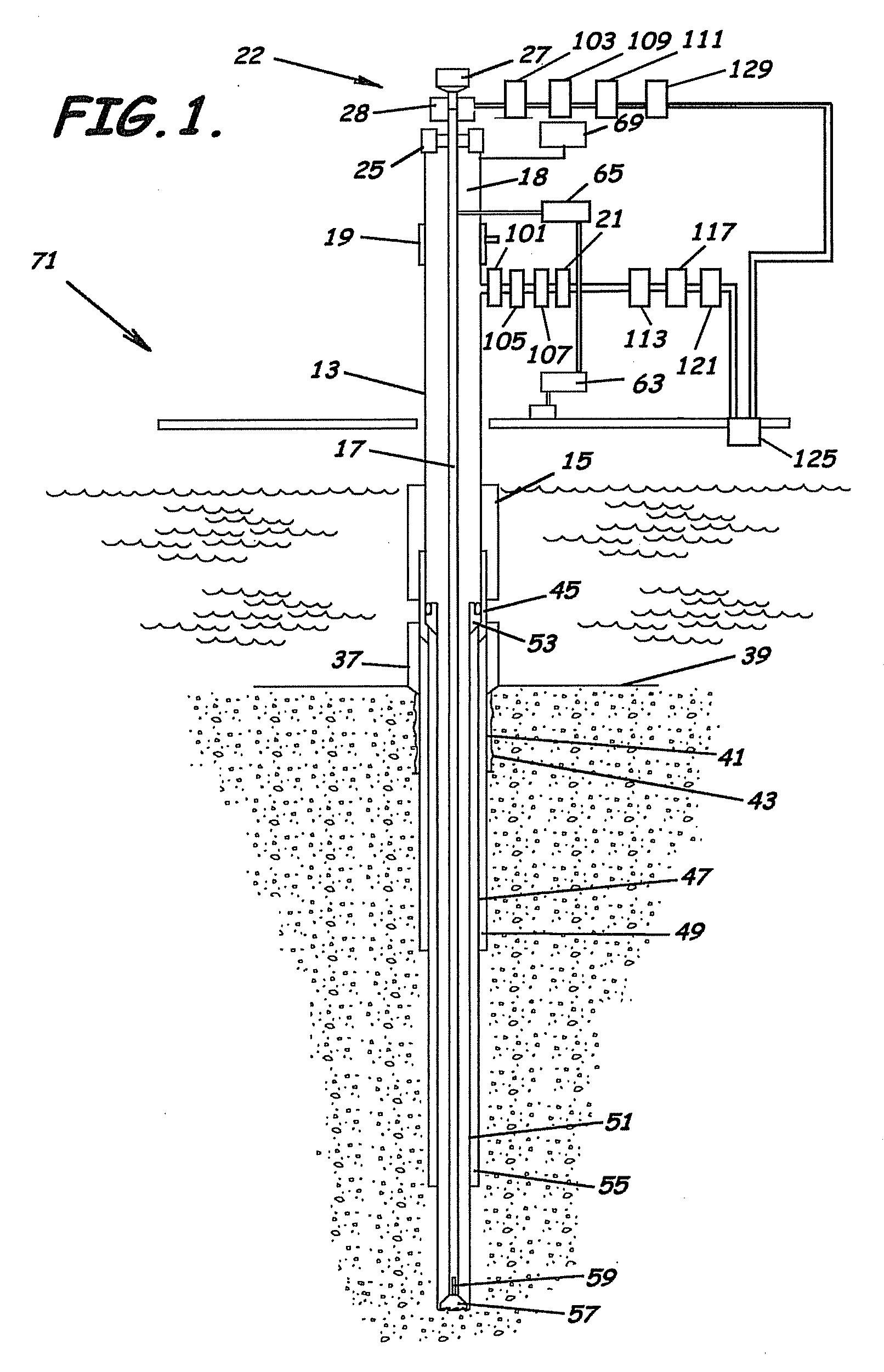
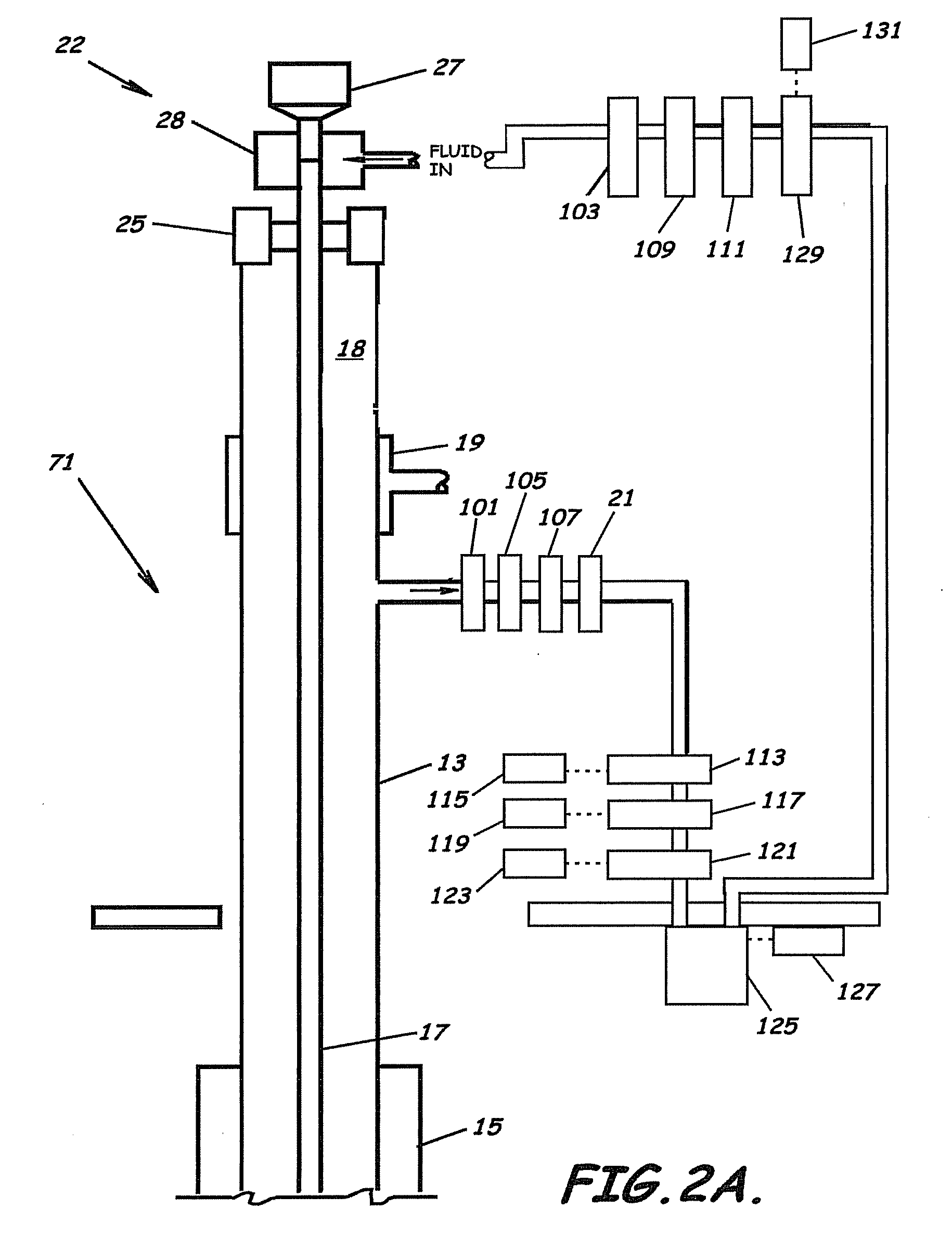
[0023]Advantageously, embodiments of the present invention provide a system, program product, and methods that can monitor and control pressure, volume, density, temperature,
fluid composition, molecular concentration of both
single phase and multiphase drilling fluid both when entering and when exiting the drilling circulation system and at any location from the surface and along the length inside the drilling string and in the annulus, i.e., either side of the U-tube, at any time or operational drilling phase. The system, program product, and methods advantageously can account for the pressure changes and other factors inside the drilling string, in the annulus, at the
choke, at the bottom of the hole, and can account for the volume of drilling fluid required to pressurize the circulation system. The system, program product, and methods can measure
compressibility of associated rocks, fluid in the rocks,
cement in the hole, the casing strings cemented in the hole, the drilling fluid, the drilling string
assembly to formulate a running description of the physical behavior of the
drilling system and all components, and can account for such
compressibility to thereby enhance dynamic density control throughout the system. Further, the system, program product, and methods advantageously can account for friction losses for any location for any
rheology and physical dimensions of the circulation system, and can determine and compensate for the existence of mud channels in the drilling string
cement. Such system, program product, and methods can dynamically manipulate the
mud weight window, and can predict maximum dynamic
bottom hole pressure at future depths to be drilled to thereby anticipate future drilling requirements to
drill at the future depth including a requirement to order supplies, people,
third party services, etc. Embodiments of the present invention can utilize surface parameters, e.g., flow rates, pressures, densities, fluid compositions (in and out);
system parameters, e.g., flow rates, pressures, densities, friction losses, temperature distributions of the drilling fluid, to predict operational parameters of the drilling fluid to thereby control drilling fluid parameters. Additionally, embodiments of the present invention can utilize gas volume and
solubility profiles in system, and can determine fracture volumes with pressure-volume-time curves /
solubility data for the drilling fluids determined by testing or in real-time during operations. Embodiments of the present invention can also incorporate compressibility and load / displacement rules or qualifications (all elements) and strategic space and time derivatives to enhance control.

