In-line milling system

a milling system and milling technology, applied in the field of products, can solve the problems of untreated emissions from the facility, unsuitable cleaning method, and unwanted agglomeration of sorbent materials in the system, and achieve the effect of minimizing the downtime required for cleaning, high volume throughput, and high volume of material being processed

Active Publication Date: 2009-08-06
OBRIEN & GERE ENGINEERS +1
View PDF5 Cites 4 Cited by
  • Summary
  • Abstract
  • Description
  • Claims
  • Application Information

AI Technical Summary

Benefits of technology

[0010]As the inventor(s) have recognized, in a high volume throughput system for sorbent delivery and duct injection, several other challenges need to be addressed. The high volume of material being processed, and the need for continuous delivery of sorbent into the system increases the need to minimize downtime required for cleaning. Cleaning the sorbent material routinely from the system is needed to ensure that good system performance is maintained. However whenever the sorbent is not being delivered to the duct for emission control, no treatment is being applied to the emissions from the facility, which is not preferable. Therefore there is a need to not only minimize the downtime of the sorbent milling and delivery system, but also a need to design the system such that sorbent delivery never stops as long as the facility is operating.

Problems solved by technology

However whenever the sorbent is not being delivered to the duct for emission control, no treatment is being applied to the emissions from the facility, which is not preferable.
A further challenge is the cleaning method itself.
Water proves to be a preferred substance for flushing residual sorbent from the mill; however, introducing water risks additional moisture and humidity to be conveyed downstream of the mill and can cause unwanted agglomeration of sorbent material in the system.
Further, if heat is used to dry the mill after a cleaning cycle, the temperature must be controlled as high temperatures can degrade the sorbent material chemistry and reduce its efficacy.

Method used


Image

  • In-line milling system
  • In-line milling system
  • In-line milling system

Examples


Embodiment Construction

[0032]Reference will now be made in detail to the present preferred embodiments of the invention, wherein like reference numerals refer to like components, examples of which are illustrated in the accompanying drawings.

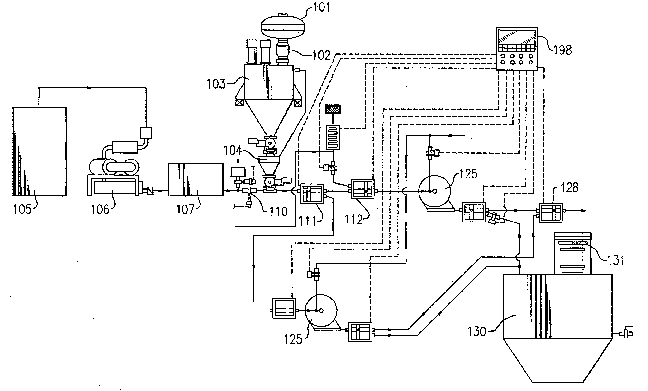
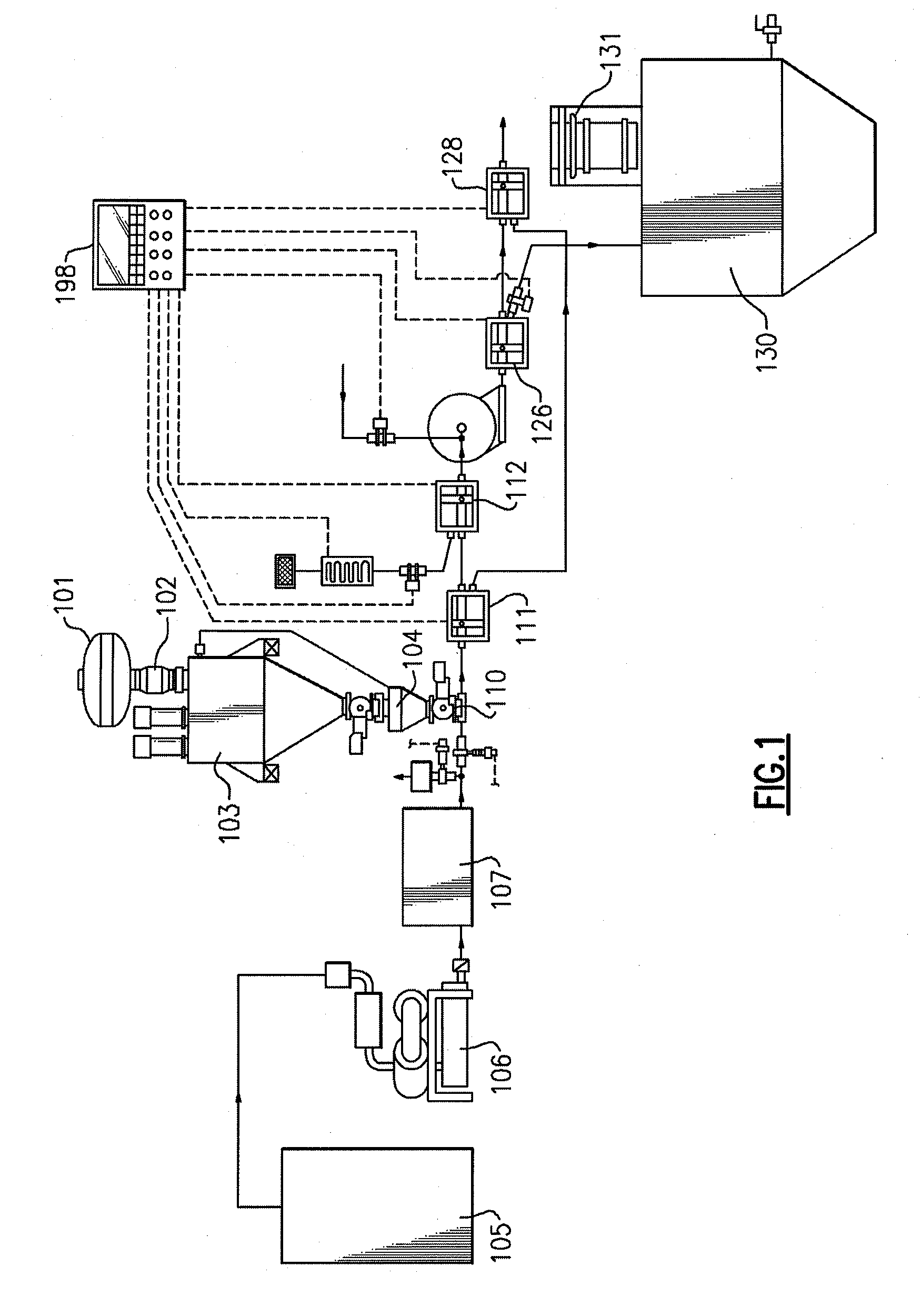
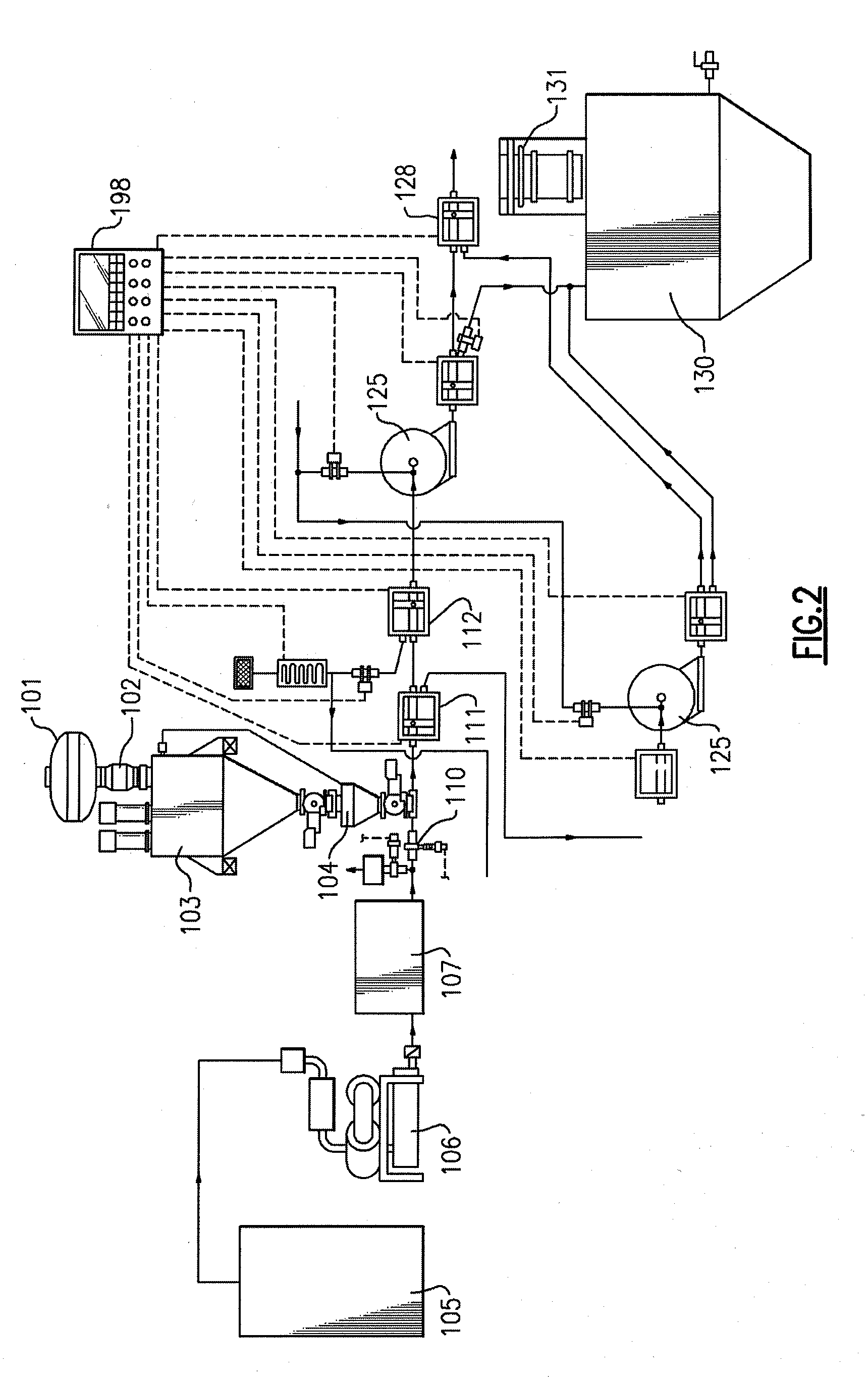
[0033]Turning to FIG. 1, a schematic view that illustrates an in-line system 100 for milling sorbent material to be used in a pneumatic conveying system according to a first embodiment of the present invention is shown. Sorbent material (not shown) enters system 100 via scalping screener 101, passes through metal separator 102 into loss-in-weight feeder 103. From loss-in-weight feeder 103, sorbent material passes through transitional vent hopper 104 into a two-way diverter assembly 110. A conditioned air stream (not shown) is provided to two-way diverter assembly 110 via dryer / chiller 105, PD blower 106, and air to air heat exchanger 107.

[0034]Within two-way diverter assembly 110, “A” diverter 111 allows sorbent material to flow toward mill 125, or diverts it as a byp...


PUM

PropertyMeasurementUnit
pressureaaaaaaaaaa
particle diameteraaaaaaaaaa
volumeaaaaaaaaaa

Abstract

The present invention provides an in-line system for milling sorbent material to be used in a pneumatic conveying system. The system provides for optimal particle size in a duct injection system, regardless of the original sorbent particle size, and is designed to prevent clogging of the milled material through the system. Methods of operation for milling, as well as cleaning the mills while providing various sorbent material by-pass configurations to minimize system down-time while enhancing material throughput and that support the unique aspects of the system, are also described in detail below.

Description

RELATED APPLICATION[0001]The present application claims priority to U.S. provisional patent application No. 61 / 023,584, filed on Jan. 25, 2008; all of the foregoing patent-related document(s) are hereby incorporated by reference herein in their respective entirety(ies).BACKGROUND OF THE INVENTION[0002]1. Field of Invention[0003]The present invention relates to the milling of product for use as a sorbent in a pneumatic conveying system. More specifically, the invention relates to an in-line system for milling (see DEFINITIONS section), and methods of operation for milling that support the unique aspects of the system.[0004]2. Description of Prior Art[0005]The market for air pollution control (APC) technology has grown tremendously since the Environmental Protection Agency (EPA) began to enforce more stringent standards via the Clean Air Act and its multiple rounds of amendments (most recently in 1990). According to BCC Research, “the total global air pollution mitigation market was w...

Claims


Application Information

Patent Timeline
Patent Type & Authority Applications(United States)
IPC IPC(8): B03B7/00B02C23/02G05B11/32
CPCB01D2251/304B01D2251/606B01D2257/302B01J20/041B02C25/00B01J20/20B01J20/3021B02C21/00B02C23/02B01J20/043
Inventor PALIN, STEPHEN C.NORMAN, JONATHANFLECKTEN, ERIC
Owner OBRIEN & GERE ENGINEERS
Why Eureka
Try Eureka