Semiconductor device and manufacturing method thereof
a semiconductor and semiconductor technology, applied in the direction of semiconductor devices, electrical devices, transistors, etc., can solve the problems of not lowering current amplification efficiency, the thickness of the gate electrode, and the above-described conventional techniques are not suitable for integration with logic circuits, so as to achieve the effect of increasing short-circuit ruggedness
- Summary
- Abstract
- Description
- Claims
- Application Information
AI Technical Summary
Benefits of technology
Problems solved by technology
Method used
Image
Examples
embodiment 1
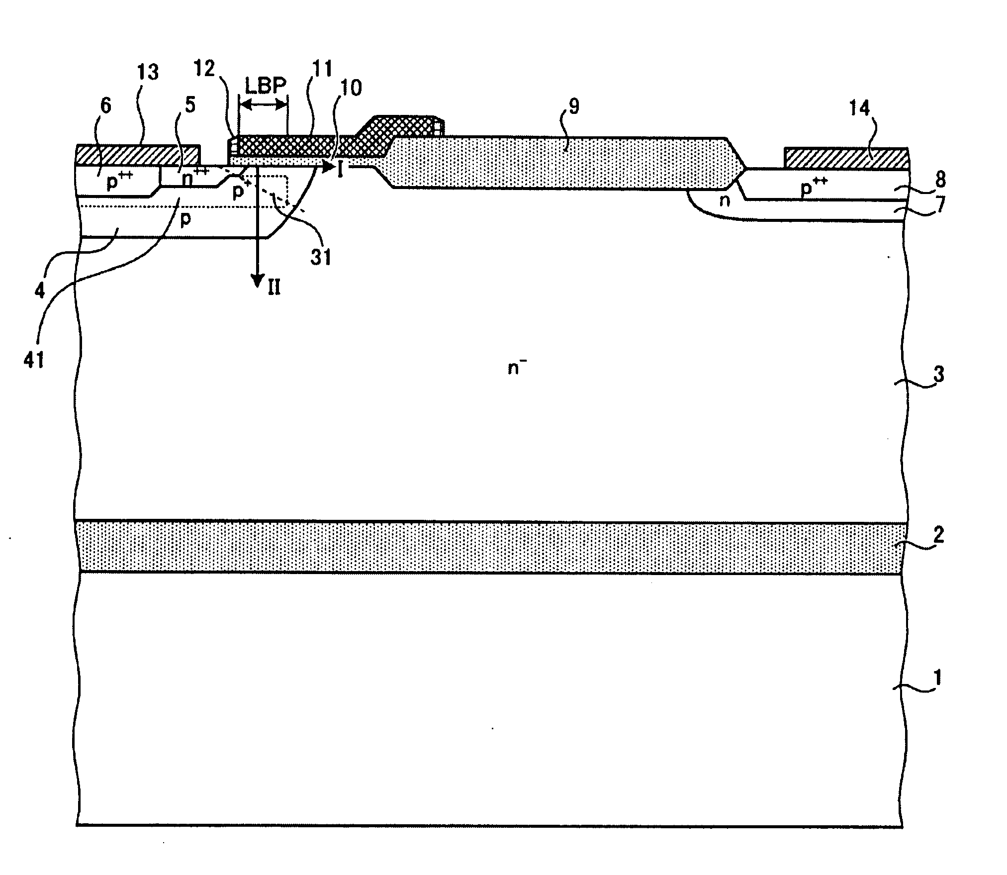
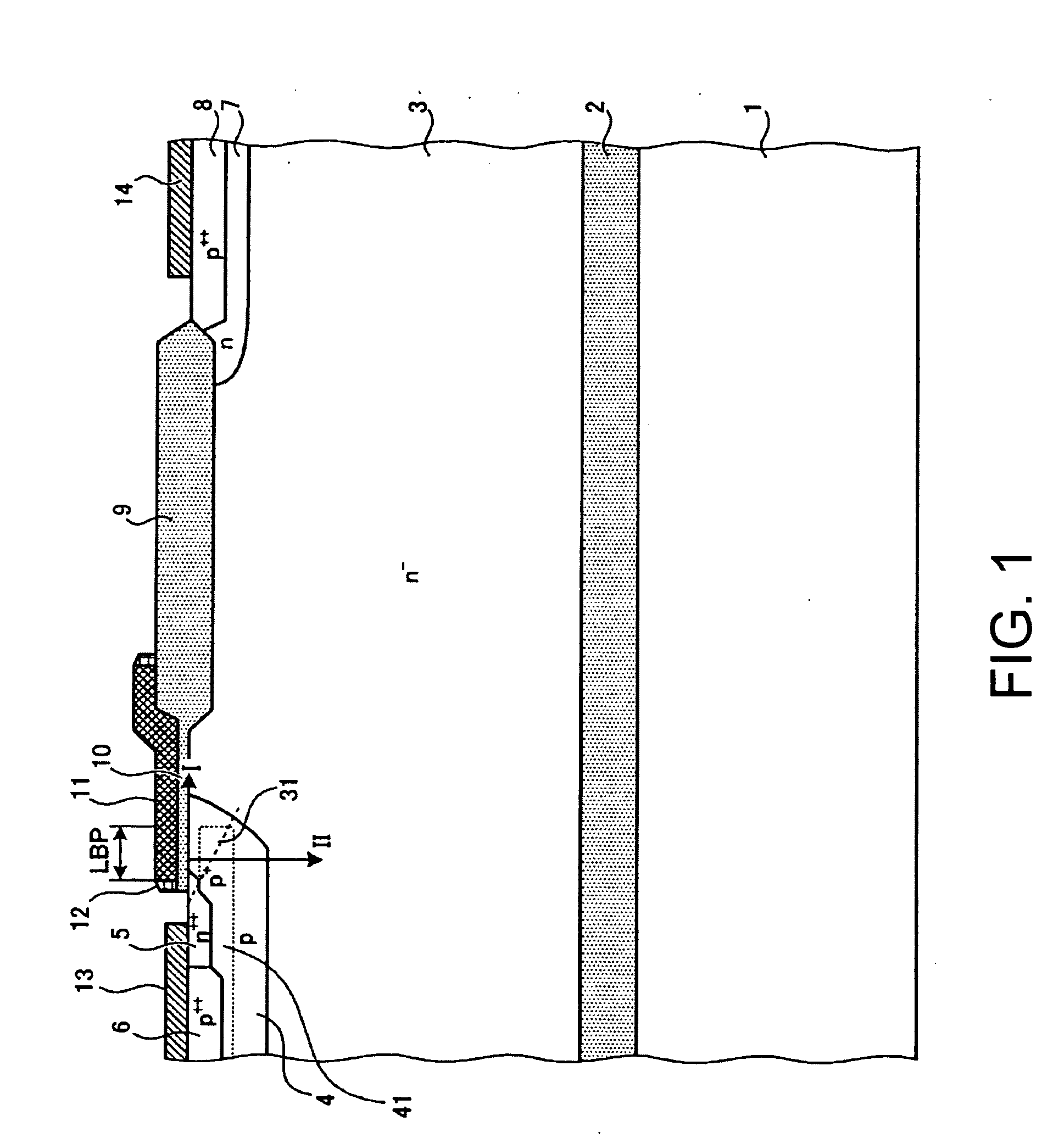
[0066]FIG. 1 shows the configuration of a semiconductor device according to the first embodiment. The semiconductor device shown in FIG. 1 is manufactured by using an SOI substrate. The SOI substrate is configured in such a manner that a buried oxide (BOX) region 2 and an n drift region 3 as a first semiconductor region are laid in this order on a support substrate 1. The BOX region 2 insulates the n− drift region 3 and the support substrate 1 from each other. A p-type body region 4 as a second semiconductor region is formed as a partial surface region of the n− drift region 3. An n++ emitter region 5 as a third semiconductor region is formed as a partial surface region of the p-type body region 4. The n++ emitter region 5 is lower in resistivity than the n drift region 3. A p++ contact region 6 is formed as a partial surface region of the p-type body region 4 so as to be in contact with the n++ emitter region 5. The p++ contact region 6 is lower in resistivity than the p-type body ...
embodiment 2
[0103]FIG. 19 shows the configuration of a semiconductor device according to the second embodiment. As shown in FIG. 19, the semiconductor device according to the second embodiment is different from the semiconductor device according to the first embodiment in that the n-type buffer region 7, the p+ collector region 8, and the collector electrode 14 are formed adjacent to the surface of the n− drift region 3 which is opposite to its surface that is formed with the p-type body region 4. As a result, the semiconductor device according to the second embodiment is a vertical IGBT structure. The semiconductor device having the vertical IGBT structure can be manufactured by using a p+ substrate to serve as the p+ collector region 8. The n-type buffer region 7 is formed on one major surface of the p+ substrate and the n− drift region 3 is formed on the surface of the n-type buffer region 7. The collector electrode 14 is formed on the other major surface of the p+ substrate. The other part ...
embodiment 3
[0105]FIG. 20 shows the configuration of a semiconductor device according to the third embodiment. As shown in FIG. 20, the semiconductor device according to the third embodiment is different from the semiconductor device according to the first embodiment in that the first n+ emitter region 5a and a second n+ emitter region 5b are formed in the p-type body region 4 and disposed away from each other. The p++ contact region 6 is formed between the first n+ emitter region 5a and the second n+ emitter region 5b so as to be in contact with them. The p+ low-resistivity region 41 is formed to surround the interfaces between the p-type body region 4 and the first n+ emitter region 5a, the p++ contact region 6, and the second n+ emitter region 5b.
[0106]The emitter electrode 13 is formed so as to be in contact with the first n+ emitter region 5a, the p+ contact region 6, and the second n+ emitter region 5b and short-circuits them. The first gate insulating film 10a which is in contact with t...
PUM
 Abstract
Description
Claims
Application Information
 - R&D
- Intellectual Property
- Life Sciences
- Materials
- Tech Scout
- Unparalleled Data Quality
- Higher Quality Content
- 60% Fewer Hallucinations
Browse by: Latest US Patents, China's latest patents, Technical Efficacy Thesaurus, Application Domain, Technology Topic, Popular Technical Reports.
© 2025 PatSnap. All rights reserved.Legal|Privacy policy|Modern Slavery Act Transparency Statement|Sitemap|About US| Contact US: help@patsnap.com


