

Optical-electrical transmission connector, optical-electrical transmission device and electronic device
- Summary
- Abstract
- Description
- Claims
- Application Information
AI Technical Summary
Benefits of technology
Problems solved by technology
Method used
Image

Examples
first embodiment
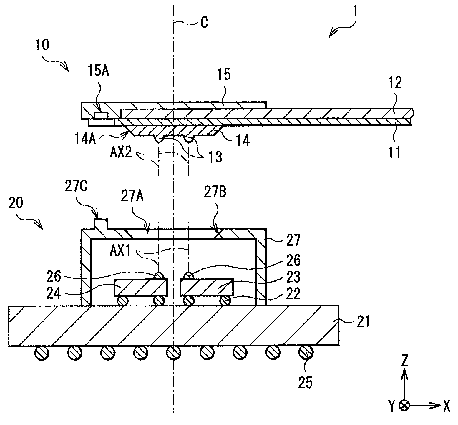
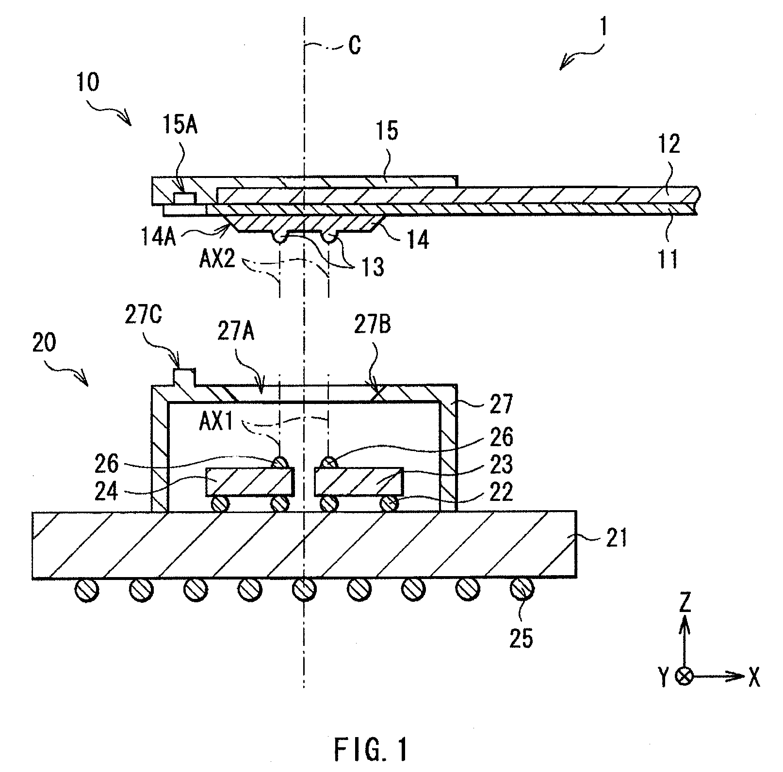
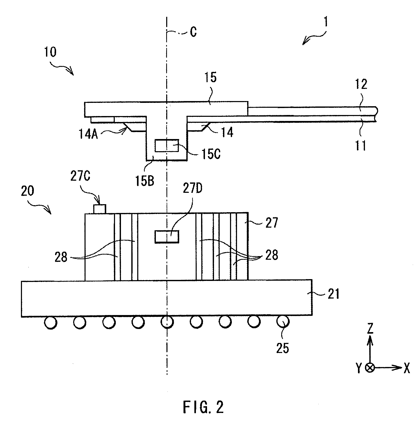
[0043]FIG. 1 shows an example of a sectional configuration of an optical-electrical transmission device 1 according to a first embodiment of the invention. FIG. 2 shows an example of a side configuration of the optical-electrical transmission device 1 shown in FIG. 1. The optical-electrical transmission device 1 provides coupling between optical transmission paths as well as coupling between electrical transmission paths, and the optical-electrical transmission device 1 includes a male connector 10 and a female connector 20. FIG. 3 shows an example of a bottom surface configuration of the male connector 10, and FIG. 4 shows an example of a top surface configuration of the female connector 20. FIG. 1 corresponds to sectional configurations taken along arrow lines A-A of FIGS. 3 and 4.
[0044]In the male connector 10, one or a plurality of light guides 12, one or a plurality of collimating lenses 13, and positioning sections 14 and 15 are arranged on a flexible board 11.
[0045]The flexib...
second embodiment
[0074]FIG. 6 shows an example of a sectional configuration of an optical-electrical transmission device 2 according to a second embodiment of the invention. FIG. 7 shows an example of a side configuration of the optical-electrical transmission device 2 shown in FIG. 6. The optical-electrical transmission device 2 provides coupling between optical transmission paths and coupling between electrical transmission paths, and the optical-electrical transmission device 2 includes a female connector 30 and a male connector 40. FIG. 8 shows an example of a bottom surface configuration of the female connector 30, and FIG. 9 shows an example of a top surface configuration of the male connector 40. FIG. 6 corresponds to sectional configurations taken along arrow lines A-A of FIGS. 8 and 9.
[0075]The same configurations, functions and effects as those in the above-described embodiment will not be further described, and only different configurations, functions and effects from those in the above-d...
application example
[0098]Next, the case where the optical-electrical transmission devices 1 and 2 according to the above-described embodiments are applied to an electronic device 3 will be described below. The case where the optical-electrical transmission device 1 is applied to the electronic device 3 will be described below as an application example.
[0099]FIG. 10 shows a schematic configuration of the electronic device 3 according to the application example. The electronic device 3 includes an operation section 31 such as a keyboard, a display section 32 such as a liquid crystal display, and a connecting section 33 rotatably connecting the operation section 31 and the display section 32 to each other. In the electronic device 3, the optical-electrical transmission device 1 performs communication between a device 34 and a device 35 by optical-electrical transmission, and as shown in FIG. 11, one female connector 20 is connected to the device 34, and the other female connector 20 is connected to the d...
PUM
 Abstract
Description
Claims
Application Information