
Medical manipulator and medical robot system

a robot and manipulator technology, applied in the field of medical manipulators and medical robot systems, can solve the problems of reducing the efficiency of the operation, so as to achieve the effect of efficient energy supply

Active Publication Date: 2009-08-06
KARL STORZ GMBH & CO KG
View PDF9 Cites 101 Cited by
  • Summary
  • Abstract
  • Description
  • Claims
  • Application Information

AI Technical Summary

Benefits of technology

[0013]It is an object of the present invention to provide a medical manipulator, which is capable of efficiently supplying energy to a needle mounted on the tip end thereof, as well as to provide a medical robot system incorporating such a medical manipulator.
[0014]Another object of the present invention is to provide a medical manipulator, which can easily be inserted through a trocar for use in endoscopic surgical operations, and which allows a plurality of needles to pierce a living body at appropriately spaced locations.

Problems solved by technology

However, even if the electrosurgical knife is replaced with a needle for supplying microwaves, since microwave energy tends to radiate from the electrical wires, the assembly is considerably inefficient.
If microwaves are supplied to a plurality of needles, which are appropriately spaced apart from each other, then it may be contemplated that the needles can perform a surgical technique over a wide region, thereby resulting in a synergetic effect and a shortened operation time.
However, in endoscopic surgical operations, since forceps are inserted through narrow trocars, even if needles are mounted onto the tip ends of such forceps, the distance between the needles is limited.

Method used


Image

  • Medical manipulator and medical robot system
  • Medical manipulator and medical robot system
  • Medical manipulator and medical robot system

Examples


Embodiment Construction

[0050]Like or corresponding parts shall be denoted by like or corresponding reference characters throughout the views.

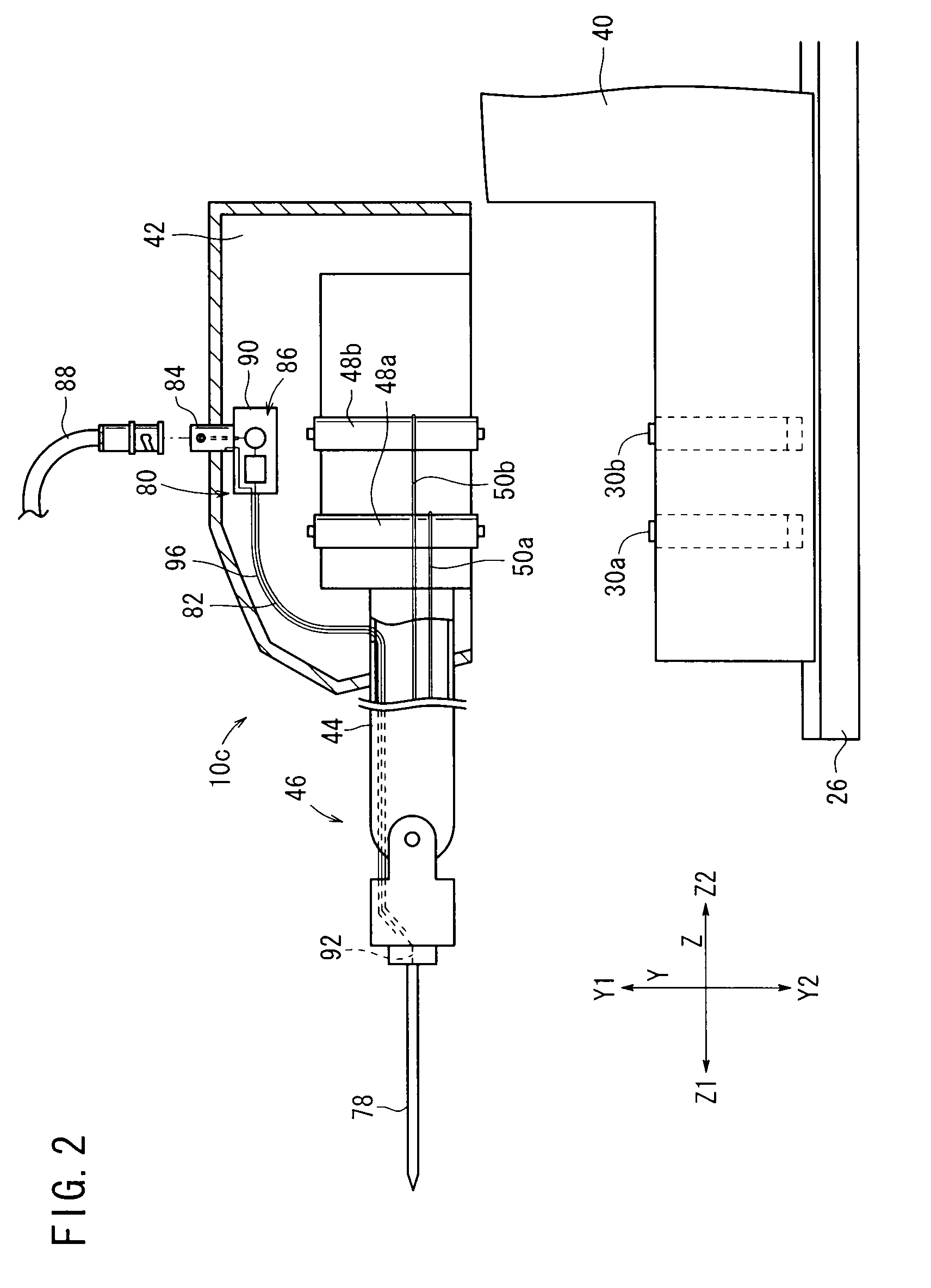
[0051]Medical manipulators and medical robot systems according to embodiments of the present invention will be described below with reference to FIGS. 1 through 19.

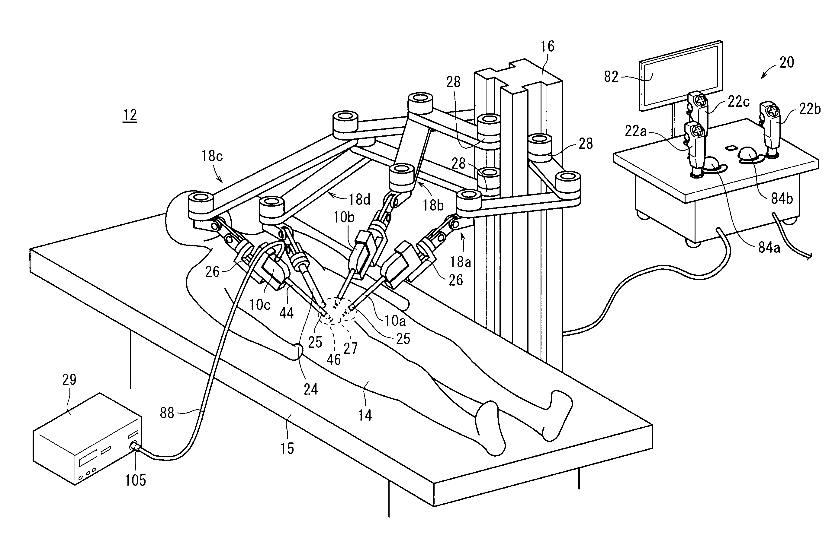
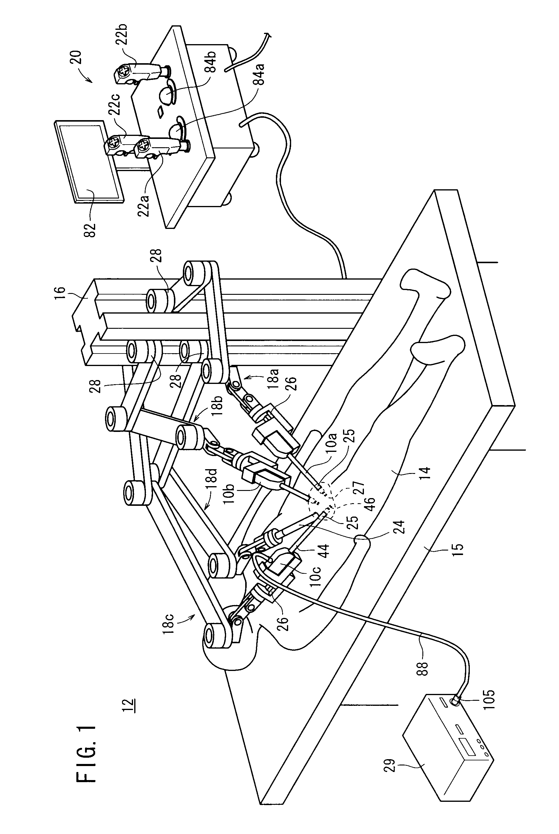
[0052]As shown in FIG. 1, a medical manipulator 10c and a medical robot system 12 according to an embodiment of the present invention are particularly suitable for performing an endoscopic surgical operation on a patient (also referred to as a “living body”) 14.

[0053]The medical robot system 12 comprises a station 16 in the form of a vertical column disposed near a surgical bed 15, four robot arms 18a, 18b, 18c, 18d mounted on the station 16, and a console (controller) 20 for controlling the medical robot system 12 in its entirety. The robot arms 18a through 18d and the console 20 may be connected to each other through a communication means comprising a wired link, a wireless link, a network, or a combinat...


PUM


Abstract

A manipulator includes a yaw axis and a pitch axis disposed as joints on a distal end of a joint shaft and which are actuatable by motors, a needle variable in orientation by the joints, a coaxial connector disposed at a position closer to a proximal end of the manipulator than the joint shaft, and a coaxial cable providing within the joint shaft at least a portion of an electrical connection between the coaxial connector and the needle. A small board providing an impedance matching circuit, and which includes a coil and a capacitor, is interposed between the coaxial connector and the coaxial cable.

Description

BACKGROUND OF THE INVENTION[0001]1. Field of the Invention[0002]The present invention relates to a medical manipulator that includes a needle mounted on the tip end of a shaft for supplying microwave energy to perform a surgical technique on an affected region of a patient, and also to a medical robot system incorporating such a medical manipulator.[0003]2. Description of the Related Art[0004]Electrosurgical knives and laser knives mainly are used to solidify, stop bleeding, and cut off affected and surrounding regions in patients. Recently, there has been proposed a medical apparatus employing microwaves. The proposed medical apparatus includes a needle for piercing a living body and a means for supplying microwave energy to the needle so as to enable the needle to generate thermal energy to perform a surgical technique, such as tissue solidification, blood stanching, or the like, on the living tissue (see, for example, Japanese Patent Publication No. 1-020617 and Japanese Patent P...

Claims


Application Information

Patent Timeline
Patent Type & Authority Applications(United States)
IPC IPC(8): A61B19/00
CPCA61B18/18A61B18/1815A61B19/2203A61B19/26A61B2017/00477A61B2019/2223A61B2019/2242A61B2019/2276A61B19/5212A61B2034/742A61B34/71A61B90/361A61B90/50A61B34/30A61B34/37
Inventor OMORI, SHIGERU
Owner KARL STORZ GMBH & CO KG
Learn More