Eureka AIR delivers breakthrough ideas for toughest innovation challenges, trusted by R&D personnel around the world.

Thin film holographic solar concentrator/collector

a solar concentrator and film technology, applied in the field of solar power, can solve the problems of affecting the supply of fossil fuels, affecting the diffraction efficiency of films, and a considerable burden on fossil fuels, and achieve the effect of increasing diffraction efficiency

Inactive Publication Date: 2009-08-13
SNAPTRACK
View PDF106 Cites 61 Cited by
  • Summary
  • Abstract
  • Description
  • Claims
  • Application Information

AI Technical Summary

Benefits of technology

The patent describes a device for collecting solar energy that uses a light guide and a photocell to convert light into electricity. The device includes a light guide with top and bottom surfaces that guide light through multiple total internal reflections to the photocell. The light guide may also include diffractive features that redirect ambient light incident on the guide and a transmissive diffractive element that guides light in the guide by total internal reflection from the top and bottom surfaces. The device may also include a solar thermal generator to produce energy. The technical effects of the invention include improved efficiency and flexibility in collecting solar energy.

Problems solved by technology

Fossil fuels are a non-renewable source of energy that are depleting rapidly.
The large scale industrialization of developing nations such as India and China has placed a considerable burden on the available fossil fuel.
In addition, geopolitical issues can quickly affect the supply of such fuel.
However, the use of solar energy as an economically competitive source of renewable energy is hindered by low efficiency in converting light energy into electricity and the variation in the solar energy depending on the time of the day and the month of the year.
Such systems, however, are complicated, often bulky and large.

Method used

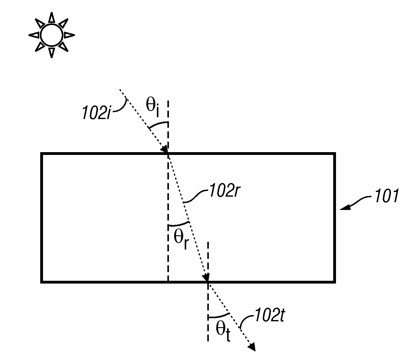
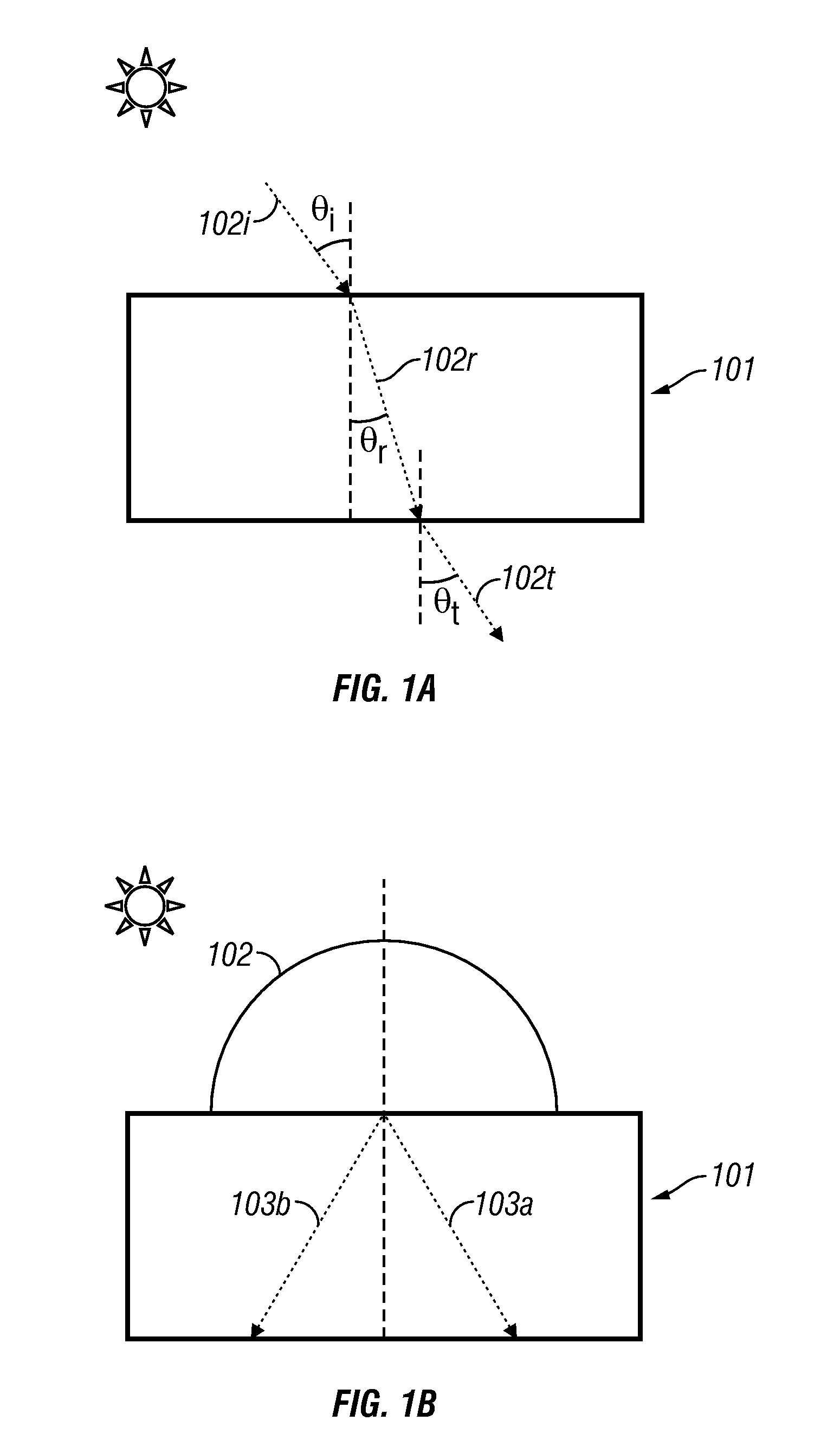
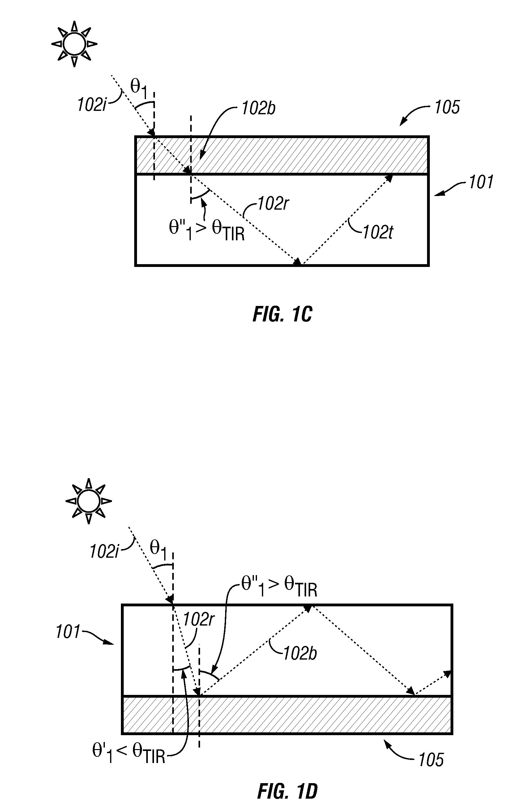

Image

  • Thin film holographic solar concentrator/collector
  • Thin film holographic solar concentrator/collector
  • Thin film holographic solar concentrator/collector

Examples


embodiment 400

[0071]FIG. 4A shows one method of fabricating an embodiment 400 comprising a volume transmission hologram. The method comprises disposing a photosensitive plate, film or layer 405 on the upper surface of a light guide 401. As described above, the photosensitive plate, film or layer 405 may be laminated or adhered to the light guide 401, for example, by an adhesive layer. This adhesive layer may be index-matched to the light guide 401. In other embodiments, the photosensitive material is coated on the light guide 401. In certain embodiments, the photosensitive plate, film or layer 405 may be referred to as a hologram recording material. The photosensitive plate, film or layer 405 may comprise photographic emulsions, dichromated gelatin, photoresists, photothermoplastics, photopolymers, photochromics, photorefractives, etc. In some embodiments, the hologram recording material may comprise a layer of silver halide or other photosensitive chemical. Diffractive features may be formed in ...

embodiment 500

[0075]FIG. 5A shows a method of fabricating an embodiment 500 comprising reflection holograms. In this embodiment, the method comprises disposing a photosensitive plate, film or layer 505 on a bottom surface of a light guide 501. The photographic plate, film or layer can be coated on or laminated to the bottom surface of the light guide 501. As described above with reference to FIG. 4A, an adhesive can be used to join the photosensitive plate, film or layer to the light guide 501. The reference laser source 508 is disposed rearward to the light guide 501 such that the reference beam is incident on the bottom surface of the light guide 501. As described above, the reference prism 506 can be used to couple the reference beam at steep angles (for e.g. θ″) to produce a beam that is a guided mode of the light guide 501. A light source 507 is disposed forward of the light guide 501 such that the object beam is incident on the upper surface of the light guide 501. The interference pattern ...

embodiment 900

[0081]For every embodiment of the stacked composite light collector described above, the light collection efficiency can be further increased by designing each light turning element to capture or collect light in different angular cones as well as light in different spectral regions. This concept is described in detail below. In the embodiment 900 shown in FIG. 9, multiple light guide layers 901, 902, 903, 904, 905 and 906 are stacked together to form a composite light collecting structure. PV cells 913 can be disposed laterally with respect to the composite light collecting structure as shown in FIG. 9. Each light guide layer 901 through 906 further comprises a light turning element comprising diffraction features or holograms 907 through 912 as shown in FIG. 9A. The different light turning elements 907 through 912 are configured to capture light incident on the light collector from the surrounding medium (e.g. air) at different angles. For example, in one embodiment light turning ...


PUM


Abstract

In various embodiments described herein, a device comprising one or more light guides that is optically coupled to one or more photocells is described. The device further comprises one or more light turning films or layers comprising volume or surface diffractive features or holograms. Light incident on the light guides is turned by volume or surface diffractive features or holograms that are reflective or transmissive and guided through the light guides by multiple total internal reflections. The guided light is directed towards the photocells. In certain embodiments, solar energy is also used to power or heat a thermal generator to heat water or produce electricity from steam. Various embodiments may comprise an air gap or an optical isolation layer disposed between the multiple light guides.

Description

CROSS-REFERENCE TO RELATED APPLICATIONS[0001]This application claims priority under 35 U.S.C. § 119(e) to U.S. Provisional Application Ser. No. 61 / 028,139 filed on Feb. 12, 2008, titled “THIN FILM HOLOGRAPHIC SOLAR CONCENTRATOR / COLLECTOR” (Atty. Docket No. QMRC.002PR), which is hereby expressly incorporated herein by reference in its entirety.BACKGROUND[0002]1. Field of the Invention[0003]The present invention relates to the field of solar power and more particularly to using micro-structured thin films to collect and concentrate solar radiation.[0004]2. Description of the Related Art[0005]For over a century fossil fuel such as coal, oil, and natural gas has provided the main source of energy in the United States. The need for alternative sources of energy is increasing. Fossil fuels are a non-renewable source of energy that are depleting rapidly. The large scale industrialization of developing nations such as India and China has placed a considerable burden on the available fossil ...

Claims


Application Information

Patent Timeline
Patent Type & Authority Applications(United States)
IPC IPC(8): H01L31/052G02B5/32F24S23/00F24S23/70F24S23/75
CPCF24J2/067G02B6/0033H01L31/0547Y02E10/52H01L31/0543G02B6/0076F24S23/12G03H1/0408G03H2001/0439G03H2001/2226G03H2001/2615G03H2001/264
Inventor BITA, IONGRUHLKE, RUSSELL WAYNEXU, GANGMIGNARD, MARC MAURICE
Owner SNAPTRACK
Why Eureka
Eureka Blog
Learn More